Four weeks after I placed an order with Farnell, the ICs haven't arrived yet. Their lead time is 1 to 3 weeks. I emailed them saying it was way past the maximum lead time they had provided me. A representative of theirs called me the next morning and told me that all the parts were already in their local warehouse, except for one. And that one part has a lead time of 32 weeks! 7 months! Well, why the heck didn't they tell me earlier? And why didn't they deliver the components that are already in their office? Why did the client have to follow up before informing him of this extraordinary situation? Uhh!
The person I spoke with told me she'll get on matter immediately and deliver the parts that are already around. She gave me the option of retaining or canceling the IC that won't be available till next year. After I said it would be good if could be cancelled, she said she'll have to check whether it can be cancelled. Argghh! Doesn't this company have a policy in place for these situations? This isn't at all what I expect from a global distribution company. Three thumbs down.
I rarely purchase from Farnell because their prices are way higher than RS Components'. The only reason I ever get from Farnell is if RS doesn't carry the part. And I only buy from RS when local suppliers don't have what I need. With this unforgivable incompetence, Farnell has slipped further than last place in my list.
Friday, June 25, 2010
Tuesday, June 22, 2010
Sayonara to Sanwa DMMs
It may be strange to hear but the only multimeters I've used over the decades are those by the Japanese company Sanwa.I've laid hands on various Made in China meters, some of which were Fluke look-alikes, but hey those meters aren't even worth having had for free.
 In my small collection I have a very old N101 (purchased c.1970s) which I inherited from my dad. I'm still using the original test leads, and have the original box and its manual (which includes a complete schematic). I really like this meter, specially its exterior design. I don't think there's a Sanwa analog meter that can beat its clean, smart, modern, look. I've burned this meter in the past--accidentally poking the VAC mains while the range switch was set to ohms. You get the shock of your life from the BZZZZT that goes off inside the meter. And you end up with deep fried resistors for lunch. Great thing about these old analogs is that they use large through-hole components which are so easy to replace. Take out the burnt component and solder in a new one and it's good to go again. No ICs to worry about. No surface mounts. Of course, accuracy isn't one of its strong points. But it's good to have one (inexpensive) analog around, even if only as a backup meter. And hey, this N101 is quickly becoming an antique. Maybe it's already appreciating in value. This unit is a keeper. I want to pass it on to one of my nephews--one who will eventually grow up to have a love for electronics/electrical work.
About two decades ago I bought my first digital multimeter--the CD721. (Sorry no pics available.) As always I wrecked this meter within a couple of years. Shot its brain with 240VAC while it wasn't expecting it--ohms range. And moreover, the plastic casing is now bloated. I can't remember exactly how that happened, but it could've been because I left it baking inside the car while it was parked in the sun--we're talking of something like 50Celsius. The CD721 is with my sister now. I have no use for that piece of junk. Her kids like playing around with it though. Yes, I have taken precautions so that the little ones won't be able to stab themselves with the probes or get themselves roasted poking into outlets.
Got a CD771 back in 2007 for around $65 to $70 (depending on what the dollar conversion rate was at that time). I don't even use my meters on a weekly basis. And yet this dang unit has already been on the blink for a year now. It just sucks. When this meter works, it works quite well. But when it's in a fit, it'll throw garbage at you. During those moments, the meter might give yo a reading of 40V while you're measuring a 5VDC circuit or it might even display "OL" meaning it's out of range. And the resistance might read several megohms when you short the probes and autoranging slows down to a crawl. To get the meter to work again I switch it off then on again. Usually after one or two such resets the meter gets its sanity back.
So in terms of ruggedness and reliability I can't but give Sanwa digital multimeters a two thumbs down. I've really become sick and tired of Sanwa DMMs that I got myself a Fluke. No cheapo. The Fluke 80 series is some 5 times pricier than the Sanwa. It hasn't arrived but I know I won't be disappointed. And that's one DMM I'm certain will proudly be on my bench and in my tool box for decades to come.
Monday, June 21, 2010
Thou shalt not turn an op amp into a comparator
Is that writ in stone? A commandment from Mt. Sinai no less?
Texas Instrument engineers Bruce Carter and Ron Mancini say that using an op amp as a comparator is a no-no because "an op amp has an output stage optimized for linear operation, while the output stage of a
comparator is optimized for saturated operation." Moreover, "the comparator is an open loop device, utilizing no feedback resistors." The op amp, on the other hand, is
Engineer James Bryant of Analog Devices has the same advice as the guys from TI.
Bryant does address the matter of building hysteresis into the op amp.
He concludes on a more positive note:
----
Reference:
Bruce Carter & Ron Mancini, Op Amps for Everyone, 3rd ed., Newnes, 2009, p. 535-538.
Texas Instrument engineers Bruce Carter and Ron Mancini say that using an op amp as a comparator is a no-no because "an op amp has an output stage optimized for linear operation, while the output stage of a
comparator is optimized for saturated operation." Moreover, "the comparator is an open loop device, utilizing no feedback resistors." The op amp, on the other hand, is
optimized for closed loop applications. The results are unpredictable when an op amp is used open loop. No semiconductor manufacturer can or will guarantee the operation of an op amp used in an open loop application.Yet more bad news:
The transistors used for op amp output stages are not switching transistors.... When saturated, they not only may consume more power than expected, they may also latch up. Recovery time may be very unpredictable. One batch of devices may recover in microseconds, another batch in tens of milliseconds. Recovery time is not specified, because it cannot be tested. Depending on the device, it may not recover at all! Runaway destruction of the output transistors is a distinct possibility in some rail to rail devices.There can be exceptions to the rule, however.
In some cases, the designer may get away with using an op amp as a comparator. When an LM324 is operated in this fashion, it hits a rail and stays there, but nothing 'bad' happens. The situation can change dramatically, however, when another device is substituted.But what if we use the op amp with positive feedback? That's no longer open loop, right? Well that's a question that Carter and Mancini don't tackle. And positive feedback is what we put into the touch sensor op amps to turn them into comparators with hysteresis. So does that make the use of op amps as comparators ok? Doubt it. Even if that solves the open loop problem, it still leaves the issue of op amps being used to saturation and slamming its output to rail. Then again maybe we'll get lucky and will be able to get away with it, depending on the op amps we use.
Engineer James Bryant of Analog Devices has the same advice as the guys from TI.
[T]he best advice on using an op amp as comparator is very simple—don't! Comparators are designed to work as open-loop systems, to drive logic circuits, and to work at high speed, even when overdriven. Op amps are designed for none of these. They are intended to work as closed-loop systems, to drive simple resistive or reactive loads, and should never be overdriven to saturation.Damn.
Bryant does address the matter of building hysteresis into the op amp.
He concludes on a more positive note:
[A]lthough op amps are not designed to be used as comparators, there are, nevertheless, many applications where the use of an op amp as a comparator is a proper engineering decision. It is important to make an educated decision to ensure that the op amp chosen performs as expected.
To do this, it is necessary to read the data sheet carefully and to consider the effects of nonideal op amp parameters on the application. Because the op amp is being used in a nonstandard manner, spice models may not reflect its actual behavior, and some experiment is advisable. Furthermore, because not all devices are typical in their behavior, some pessimism is warranted when interpreting the experimental results.
----
Reference:
Bruce Carter & Ron Mancini, Op Amps for Everyone, 3rd ed., Newnes, 2009, p. 535-538.
Sunday, June 20, 2010
A purely analog touch sensor
My sister's family and I spent the afternoon together last Sunday. Had a late lunch at a fine dining restaurant. Food was great. Unfortunately the kids still need years to develop a taste for good food. Their dad said he'd just bring them to Krispy Kreme after lunch to fill their bellies.
At least twice during the meal the 5- and 4- year old had to go to the washroom. Being the good and lovable uncle I accompanied them.Well, it proved to be an adventure for the boys. The urinals in the air conditioned and plush restrooms had infrared sensors to detect the presence of, well, humans. As can be expected the brats had a ball playing with them, tripping them off with their hands and watching as the gizmo flushed water down.
That evening it occurred to me that I could easily design a circuit the kids can have fun with to turn on a light or just an LED. I already have a circuit installed in my home that switches on the ceiling lights whenever I cross the hallway. It's a windowless area and is pitch black at night. With the circuit I don't have to go back and switch off the lights. The sensor is a Keyence PZ-51 infrared transmitter-receiver with an NPN output, which I set up as a reflective system with the emitter and detector side by side. When something/someone reflects enough of the infrared beam back to the receiver the circuit gets triggered and the lights are switched on for a little over half a minute. A 3-second beep sounds right before the lights go out to warn the person.
Given my experience with photoelectric sensors and the fact that I still have a number of these Keyence products I got from a sale almost a decade ago, I started designing a circuit based on photosensors. But I hadn't even drawn a single schematic when it hit me that this was just overkill. Using an industrial part like the Keyence didn't seem right. Worse, it isn't kid-proof at all!
I needed something simpler and more rugged, something more or less immune to the bashing, smashing, "crayoning," drooling, and what-have-you the sensor will be up against and subjected to with a brood of 2-, 3-, 4-, and 5-year olds. So it occurred to me--Why not detect the 60Hz hum that everyone in the city conducts? That way the sensor could be any conductor--a length of wire, small thumb-sized metal sheet, maybe even the door handle of a cabinet.
Mulling over the circuit requirements, it seemed to me that what had to be done was to amplify the signal from the human touch and pass it through a comparator with hysteresis to get a good clean digital output. I hit the breadboard and configured one of the op amps of a MCP6232 dual op amp as a noninverting amplifier with a gain of 100 and the other as a comparator. Well, surprisingly, it worked!
Oscilloscope showed, however, that there was a lot of high frequency noise being amplified as well. So I figured I'd add a low pass filter (LPF) at the front end (before the amplifier) with a cutoff frequency (Fc) of around 120Hz .To try it out I used a good round figure of 100Kohm and 10nF which gave an Fc of 160Hz.(equation is 1/(2πRC)). Sure enough it cleaned up the signal pretty well.
The design was practically finished and I could feed the 60Hz pulse train output of the comparator to a microcontroller and have that MCU process the signal and turn on lights and buzzers, etc. for, say, a specified amount of time. It can even reject rapid multiple "button presses" to prevent the light from being turned too many times a minute. Or it can process such multiple contacts as a code to turn the load on for a certain amount of time or certain fashion, etc. Once the analog end was able to provide a reliable signal, the MCU could do the rest. And if the MCU had an onboard comparator then we need only filter and gain the input signal before sending it to the MCU.
But I wasn't satisfied. I wanted to push myself and create an output (from the op amps) that stayed high (Vcc) the moment the comparator was triggered and then drop out (go to ground) once the 60Hz pulse train ceased. In other words, if I hooked up the output to trigger an NPN, the transistor would be completely and continuously on while the user was touching the sensor.
So what I had to do was to convert that pulse train from the comparator to a DC signal that would rise to and remain above a certain minimum voltage while the user was touching the sensor. My solution? An LPF with a Fc of <60Hz.
As a first cut, I used a 1uF tantalum and 100Kohm to give an Fc of 1.6Hz. I then got another MCP6232 and configured one of the op amps as a noninverting comparator (with no hysteresis). The output of the passive LPF was then fed directly into the noninverting input of the op amp.
Lo and behold! I got what I wanted. Well, almost. Not surprisingly the long RC constant of the 1.6Hz LPF caused a hell of a delay in the response of the second comparator. After the user touches the sensor it took tens of milliseconds for the voltage to ramp up to the trip point of the comparator and then after the sensor ceased detecting contact, it took about a hundred milliseconds for the voltage to decay below the trip point. Very slow and humanly noticeable delay.
To alleviate this, I had to decrease the RC constant which meant increasing the Fc. I chose 6Hz. Oscilloscope showed a very significant increase in ripple voltage. And this of course meant that the comparator (remember, it had no hysteresis) could rapidly go high and then low and then high again as the voltage was passing the comparator trip point. And in fact, tests showed that this does happen every once in a while. This meant that hysteresis had to be designed into the circuit.
Which I did. I added positive feedback using two resistors. When I tried the circuit it was a dud. Why? Because the output of the passive LPF is high impedance. The noninverting input of the comparator is very high impedance but with the positive feedback resistors also connected to the noninverting pins of the op amp that just changes the circuit characteristics. Solution was simple but required the use of another op amp. The LPF had to be buffered by a voltage follower (unity gain amplifier). This low impedance signal could then be fed to the comparator with hysteresis.
 The following is the final circuit (for now) after tweaking the values for the LPFs, hysteresis, comparator voltage reference, etc. Load resistor RL is necessary and has to be high value. The lower the value the more attenuated the signal becomes. I used a 3Meg in the test circuit. The front end LPF has a Fc of 72Hz. You might notice the "coax." in the schematic. A coaxial cable is needed only if the sensor--a fingernail-sized touch plate for instance--will be located more than a few centimeters from the circuit board. Any plain old conductor acts as an antenna picking up the 60Hz hum; and the longer the conductor the higher the amplitude of the signal. At the amplifier gain of 100, a wire longer than 20 centimeters will transmit a large enough signal to trigger the first comparator. I've actually tried using a meter-long coaxial wire and it does work--the circuit is not triggered unless the far end of the coax is touched. The copper braid (shield) of the coax must be electrically connected to circuit ground.
Note that amplifier A3 is no longer a voltage follower that buffers the 6Hz LPF, but a noninverting amplifier with a gain of 2. The reason is that the buffered LPF signal was approx 2.3VDC with a ripple voltage of around 850mV peak to peak. The upper threshold trip voltage of the comparator A4 is about 1.8VDC. This is no problem when the sensor is fully touched--that is, output of A1 reaches the positive rail (and you get a quasi rectangular pulse train, not a half sine wave). But when A1output is weak (low amplitude but is above the upper threshold trip voltage of comparator A2) the duty cycle of the output of A2 drops and so there is much less on time for CF2 to charge, resulting in a much lower average DC of the LPF output. This causes comparator A4 to fail to trigger. Thus, it was necessary to gain the LPF output to make sure that when A2 trips, A4 will trip too. Both comparators are referenced to 30% Vcc.
Finding the equations for determining the upper and lower threshold voltages of the comparators has been a headache. Still is. The commonly given equations in textbooks are for op amps/comparators using a bipolar power supply. I'm using a single supply. I did find single supply equations in the datasheet for the MCP6541 comparator. However, measurements using an oscilloscope (see below) do not tally with the results from the equations. Perhaps input signals to comparators A2 and A4 need to be buffered.
What follows are oscilloscope (Rigol 1102E) screenshots of the circuit in action. Refer to the schematic for test points P1 to P4.

Test point: P1
Output of A1 when sensor (a 14-cm AWG 22 wire) has not been touched. As can be seen the measured frequency is 60.2Hz and Vpp = 720mV

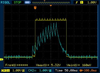
Test point: P1
Output of A1 when sensor touched. The amplifier saturates. (The Vpp as measured by the scope can't be right of course given the 1.00V/div)

Ch1 test point: P2
Ch2 test point: P1
Ch1: 2.00V/div
Ch2: 1.00V/div
Trigger: Auto, Ch2, 200mV, rising edge
Sensor touched. The output of comparator A2 is almost a square wave. The output of A1 is coming close to square wave. (The scope's Vpp measurement of A1 output is now correct)

Ch1 test point: P2
Ch2 test point: P1
Ch1: 2.00V/div
Ch2: 1.00V/div
Trigger: Auto, Ch2, 200mV, rising edge
Sensor not touched.

Ch1 test point: P3
Ch2 test point: P1
Ch1: 2.00V/div
Ch2: 1.00V/div
Trigger: Auto, Ch2, 200mV, rising edge
Sensor is touched. In the above screenshot output of A3 has already stabilized. With the gain of 2 the LPF output reaches positive rail.

Ch1 test point: P3
Ch2 test point: P2
Ch1: 2.00V/div
Ch2: 1.00V/div
Trigger: Auto, Ch2, 200mV, rising edge
Sensor is touched.

Ch1 test point: P2
Ch2 test point: P1
Ch1: 2.00V/div
Ch2: 1.00V/div
Time base:10.0ms/div
Trigger: Single sweep, Ch1, 200mV, rising edge,
Here we see the very moment A1 output trips comparator A2

Ch1 test point: P2
Ch2 test point: P1
Ch1: 1.00V/div
Ch2: 1.00V/div
Time base: 500microsec/div
Trigger: Single sweep, Ch1, 200mV, rising edge,
This is a zoomed in portion of the preceding single sweep capture. Cursors have been turned on and manually adjusted to the point of intersection between the output of A1 and A2. The scope measures the hysteresis band at 840mV. Comparator A2 upper threshold voltage = 1.88V, lower threshold voltage = 1.04V

Ch1 test point: P3
Ch2 test point: P1
Ch1: 1.00V/div
Ch2: 1.00V/div
Time base: 20.0ms/div
Trigger: Single sweep, Ch1, 200mV, rising edge,
This clearly shows that because of the RC constant of the 6Hz LPF there will be a delay before A4 output goes high.

Ch1 test point:P4
Ch2 test point: P1
Ch1: 1.00V/div
Ch2: 1.00V/div
Time base: 20.0ms/div
Trigger: Single sweep, Ch1, 200mV, rising edge
The delay between touching the sensor and A4 output going high can be seen here. Also shows the clean digital output of A4. The ripple voltage is due to the power supply.

Ch1 test point: P3
Ch2 test point: P2
Ch1: 1.00V/div
Ch2: 1.00V/div
Time base: 50.0ms/div
Trigger: Single sweep, Ch2, 200mV, rising edge
Rise and decay of A3 output in relation to comparator A2 output

Ch1 test point: P3
Ch2 test point: P2
Ch1: 1.00V/div
Ch2: 1.00V/div
Time base: 20.0ms/div
Trigger: Single sweep, Ch2, 200mV, rising edge

Ch1 test point: P4
Ch2 test point: P2
Ch1: 2.00V/div
Ch2: 1.00V/div
Time base: 20.0ms/div
Trigger: Single sweep, Ch2, 200mV, rising edge
A4 output in relation to A2 output. What is most evident is the large delay in A4 output droput

Ch1 test point: P4
Ch2 test point: P2
Ch1: 2.00V/div
Ch2: 1.00V/div
Time base: 2.0ms/div
Trigger: Single sweep, rising edge, Ch2, 200mV
This is a zoomed in portion of the preceding capture. Cursors are on to measure the delay between comparator A2 output and A4 output. In this particular case it's 3.5ms

Ch1 test point: P4
Ch2 test point: P2
Ch1: 2.00V/div
Ch2: 1.00V/div
Time base: 2.0ms/div
Trigger: Single sweep, Ch2, 200mV, rising edge
This is a zoomed in portion of the second to the last capture. Cursors are on to measure the delay between comparator A2 dropout and A4 dropout. In this case it's 57ms.
Ch1 test point: P4
Ch2 test point: P3
Ch1: 1.00V/div
Ch2: 1.00V/div
Time base: 50.0ms/div
Trigger: Single sweep, rising edge, Ch1, 1.0V

Ch1 test point: P4
Ch2 test point: P3
Ch1: 1.00V/div
Ch2: 1.00V/div
Time base: 2.0ms/div
Trigger: Single sweep, Ch1, 1.0V, rising edge
This is a zoomed in portion of the preceding capture. Cursors are on to measure the upper threshold trip voltage of comparator A4. In this case it's 1.80V.

Ch1 test point: P4
Ch2 test point: P3
Ch1: 1.00V/div
Ch2: 1.00V/div
Time base: 2.0ms/div
Trigger: Single sweep, Ch1, 1.0V, rising edge
This is a zoomed in portion of the second to the last capture. Cursors are on to measure the lower threshold trip voltage of comparator A4. In this case it's 880mV. The hysteresis band = 920mV.

Ch1 test point: P4
Ch2 test point: P1
Ch1: 1.00V/div
Ch2: 1.00V/div
Time base: 50.0ms/div
Trigger: Single sweep, rising edge, Ch1, 1.0V
A4 output in relation to A1 output.

Ch1 test point: P4
Ch2 test point: Vcc
Ch1: 1.00V/div
Ch2: 1.00V/div
Time base: 20.0ms/div
Trigger: Single sweep, Ch1, 1.0V, rising edge
This one shows the ripple voltage present in Vcc. Also shows how close to the rail A4 output is.
---------------------
Addendum
June 20 11:00pm
I reduced the cutoff frequency of the front end LPF to 1.6Hz by changing CF1 to 100nF. Touching the sensor didn't even trigger A2. I then increased the gain of A1 to 400. Didn't work either. I couldn't get A1 and A2 to have the outputs of A3 and A4 respectively. Seems there are no shortcuts.
Monday, June 14, 2010
Thermometer using a thermocouple, instrumentation amplifer, and microcontroller

- thermocouple cold junction temperature and temperature of IC that measures the cold junction temperature
- IC temperature sensor tolerance
- op amp offset voltage
- offset voltage drift
- mismatched resistors in the instrumentation amplifier
- resistor value drift
- resistor noise
- gain resistor value and stability
- op amp noise
- common mode rejection
- ADC reference voltage tolerance/drift
- ADC quantization errors
- noise from digital circuits affecting analog circuit
- EMI, RF, and 50/60Hz power line hum and its harmonics
Circuit Details
A type K thermocouple (TC) is used to sense temperature. Its + and - output are both level shifted to Vref/2, where Vref = 4.096V. An instrumentation amplifier made from three of the quad op amp MCP609 amplifies the TC voltage by 200 and removes the level shift voltage. Reference pin of the IA is connected to +0.4V in order that TC may be able to sense temperatures less than the cold junction (CJ) temperature. The Microchip PIC 16F690's 10-bit ADC digitizes gained TC voltage and the level shift voltage applied to IA ref pin. The latter is then subtracted from the former, thus leaving only the amplified TC voltage. This value now corresponds to a temperature relative to the CJ temperature. A lookup table (values are stored in a 24-element, 1-dimensional array) is used to determine the temperature of TC to within 20 degrees Celsius. Interpolation is then used to determine temperature to within 1 degree. CJ temperature is sensed by a Microchip MCP9700 temperature sensor. The ADC digitizes its output and firmware converts it to degrees Celsius. Actual thermocouple temperature is obtained by adding CJ and TC. Temperature range that can be measured is approximately between -40 to 420 Celsius. I really don't have much need for a thermometer measuring anything colder than a freezer, so the level shifting voltage at the IA reference pin need not be greater than 0.5V. On the other hand I do want the circuit to be able to measure high temperatures, >400 Celsius--thus the need to keep the level shifting voltage as low as possible. Decreasing the gain is an option but I can't get myself to part with the nice round figure of 200.
AIA1, AIA2, and AIA3 are configured as a classic three-op amp instrumentation amplifier. R1 = R2 = R3 = R4 = R5 = R6 = 20K. Gain is set by RG and is given by the equation (2R1/RG + 1). ALPF (1/4 of the MCP609) is used as an active low pass filter. Given the 100K 5% carbon resistor and 1uF tantalum capacitor cutoff frequency is 1.6 Hz with a 20dB rolloff. Op amp has a gain of 1. R1 to R6 are 5% carbon resistors which have been measured using a DMM to be within 1% of each other. Gain resistor is a 5% carbon measured at 201 ohms.
VREF (MCP1541) output is 4.096V and is used by ADC as voltage reference. It is also used for the level shift voltages since maximum gained TC output cannot exceed voltage reference voltage. Level shifting voltage VLS1 for TC must be equal to Vref/2, because output of AIA1 = E1 + (E1-E2)*R1/RG and output of AIA2 = E2 - (E1-E2)*R1/RG. The plus and minus (E1-E2)*R1/RG output is symmetrical for both op amps. VLS2 is injected into Vin+ of the difference amplifier to level shift the gained and common-mode-subtracted TC voltage. This is necessary in order to measure temperature when TC is colder than cold junction temperature. Without this level shift any TC temperature below CJ would be result in zero reading because of the single supply. VLS2 is sampled by ADC whenever reading the thermocouple temperature so that it can be deducted from it. Cold junction temperature is read by TS (MCP9700) and added to the computed thermocouple temperature. Ideally TS is placed in contact with the isothermal block to measure cold junction temperature of thermocouple leads.
Cf1a, Cf1b, Cf2a, and Cf2b are ceramic capacitors and are absolutely essential. Without them noise gets injected and IA outputs garbage. 0.1uF capacitor filters out 60Hz noise of metal casings of 60VAC appliances to which thermocouple can come into contact with. 1nF filters out high frequency noise that gets conducted by thermocouple wire acting as an antenna. Capacitors should be placed close to the IA input pins.
Separate VDD and ground connections should be made for analog and digital circuits to reduce digital noise from being injected into analog circuit. A "star" connection should be employed. All op amps are decoupled with 0.1uF caps. (See Analog Devices AD623 Instrumentation Amplifier datasheet Rev.C p.13.)
Some Equations
1. Determining cold junction temperature as measured by a Microchip MCP9700 temperature sensor
MCP9700 output at zero Celsius = 500mV
Let
t = temperature in Celsius (negative when below zero)
V = MCP9700 output voltage = 500mV + 10mV per degree Celsius
CJ = 10-bit ADC reading of MCP9700 output, with the ADC using a 4.096 voltage reference
V = 0.5 + 0.01t
CJ = (0.5 + 0.01t)*1024/4.096
CJ = (0.5 + 0.01t)*250
Therefore
t = CJ/2.5 - 50
2. Determining thermocouple temperature by use of a lookup table and interpolation
Let
TCm = thermocouple voltage at temperature m, where m = -60, -40, -20, 0, 20, ..., 400 Celsius
TCn = thermocouple voltage at temperature n, where n = m + 20
TCr = thermocouple voltage at temperature r -- the temperature of the thermocouple junction relative to the cold junction
s = number of degrees Celsius = r - m
Given that temperature r lies between m and m+20
TCr = TCm + s(TCn - TCm)/20
Given TCr and a table of values for thermocouple at various temperatures we need to look for s in order to determine r. Solving for s:
s = (TCr - TCm)*20/(TCn - TCm)
Temperature at which thermcouple junction is relative to the cold junction is therefore:
r = m + s
Actual temperature of the thermocouple joint is r + t, where t = cold junction temperature
Actual thermocouple output is gained by instrumentation amplifier and then digitized by 10-bit ADC referenced to 4.096 volts. Therefore thermocouple reading that is output by the ADC is = TCr*G*1024/4.096 = TCr*G/4, where G = gain of the IA. Because of this the table of thermocouple values for TCm and TCn are multiplied by G/4 before being used in the above equations.
Sunday, June 6, 2010
Does it really show?


Was just fooling around with image processing software. Take any photo or pic, blur it till it's but an unrecognizable goop of colors, tweak its brightness, contrast, color composition, etc and you have what ends up in the background of this artwork.
Both backgrounds use the same original drawing/painting. They've just been manipulated quite differently.
Microchip logo and name filched from one of their pdf docs
Me? A PIC fanboy?
Tuesday, June 1, 2010
Macros and Defines for the PIC Baseline and Mid-Range Microcontrollers
[I had this article up on my website about a year or so ago. I've changed ISP and that website is now defunct. I'm posting it here since it may be useful to PIC newbies. I personally still use these macros and defines. Can't do assembly without them.
Because blogspot truncates text beyond a certain width, I suggest you copy the include file and paste it in MPLAB or a text editor so you can see all the comments to the right of the code.]
The following include file contains a good number of macros that I've created to make writing code a little easier for the PIC. Also makes the code shorter--albeit only apparently--and easier to read and understand. As in my case, you'll probably find the relational macros (e.g., <, >=, <>0, etc.) the most useful and most used. I'd tear my remaining hair out if I didn't have these macros.
You won't fail to notice that I have four defines each for the btfss and btfsc instructions. I really have a difficult time with these two. The reason is because they force me to think in terms of skipping the next instruction when the test condition is true. I don't know about you but I find it way easier and natural to think of performing the next instruction should the bit test be true. To address this quirk of mine (and in retaliation against what seems to be the defacto assembly way), I've redefined btfsc and btfss as "do next" instructions. "dnx" translates into "do next."
While on the subject of mnemonics, the ones I use for the other macros are as follows:
bit0 = bit is equal to zero
bit1 = bit is equal to one
lt = less than
gt = greater than
eq = equals
not = not
l = literal
lit = literal
f = file register
w = the w register
dest = destination
If you don't like the mnemonics above then by all means change them to something that suits you. Feel free to make up your own macro labels/names.
One very important caveat: Do always keep in mind that these are macros and will be expanded inline (i.e., the macro label will be replaced by the lines of assembly instructions). As such make sure you don't write something like:
This code will fail when reg1 < reg2. The second macro has two lines of assembly and thus when reg1 < reg2 the second line of the macro will be executed along with whatever instructions come after it. The moral is: Never have any (multi-instruction) macros right after a dnx macro.
Now here's the include file that I #include in all my PIC Baseline and Mid-Range asm files.
Because blogspot truncates text beyond a certain width, I suggest you copy the include file and paste it in MPLAB or a text editor so you can see all the comments to the right of the code.]
The following include file contains a good number of macros that I've created to make writing code a little easier for the PIC. Also makes the code shorter--albeit only apparently--and easier to read and understand. As in my case, you'll probably find the relational macros (e.g., <, >=, <>0, etc.) the most useful and most used. I'd tear my remaining hair out if I didn't have these macros.
You won't fail to notice that I have four defines each for the btfss and btfsc instructions. I really have a difficult time with these two. The reason is because they force me to think in terms of skipping the next instruction when the test condition is true. I don't know about you but I find it way easier and natural to think of performing the next instruction should the bit test be true. To address this quirk of mine (and in retaliation against what seems to be the defacto assembly way), I've redefined btfsc and btfss as "do next" instructions. "dnx" translates into "do next."
While on the subject of mnemonics, the ones I use for the other macros are as follows:
bit0 = bit is equal to zero
bit1 = bit is equal to one
lt = less than
gt = greater than
eq = equals
not = not
l = literal
lit = literal
f = file register
w = the w register
dest = destination
If you don't like the mnemonics above then by all means change them to something that suits you. Feel free to make up your own macro labels/names.
One very important caveat: Do always keep in mind that these are macros and will be expanded inline (i.e., the macro label will be replaced by the lines of assembly instructions). As such make sure you don't write something like:
dnxgteq    reg1, reg2             ; check if reg1 >= reg2
addlf      0xA, reg3              ; do this if it is
; other instructions follow here
This code will fail when reg1 < reg2. The second macro has two lines of assembly and thus when reg1 < reg2 the second line of the macro will be executed along with whatever instructions come after it. The moral is: Never have any (multi-instruction) macros right after a dnx macro.
Now here's the include file that I #include in all my PIC Baseline and Mid-Range asm files.
; ==================================================================================
;
;      Defines and Macros
;
;      Include this file in all PIC Midrange assembly files
;      Edwardson Tan
;      April 2007
;
; ==================================================================================

      ;------------------------------------------------
      ; do next instruction if bit = 1 (skip next instruction if bit = 0)
      #define      donextif1    btfsc
      #define      dnxbit1      btfsc
      #define      dnxtrue      btfsc
      #define      dnxhigh      btfsc
      ;------------------------------------------------


      ;------------------------------------------------
      ; do next instruction if bit = 0 (skip next instruction if bit = 1)
      #define      donextif0    btfss
      #define      dnxbit0      btfss
      #define      dnxfalse     btfss
      #define      dnxlow       btfss
      ;------------------------------------------------


      ;------------------------------------------------
      ; copies the contents of one register to another
      ; same as macro copyregister
movff macro      reg1,reg2
      movfw      reg1
      movwf      reg2
      endm
      ;------------------------------------------------


      ;------------------------------------------------
      ; copies a literal value to a register
      ; same as macro copyliteral
movlf macro      literal, register
      movlw      literal
      movwf      register
      endm
      ;------------------------------------------------


      ;------------------------------------------------
      ; "sets" a register (opposite of "reset")
      ; places a literal value of 1 in the register
setf  macro      register
      movlw      .1
      movwf      register
      endm
      ;------------------------------------------------


      ;------------------------------------------------
      ; gets the high bits <12:8> of program counter PC and pastes them into PCLATH
      ; this routine is necessary just prior to doing a table read (retlw)
      ; with a computed goto, i.e., with a ADDWF PCL,f instruction
getpchigh macro  routine_label         ; routine_label is the name/label of the subroutine
      movlw      high routine_label    ; "high" is an arithmetic operation that retrieves the high bits of routine_label
      movwf      PCLATH
      endm
      ;------------------------------------------------


      ;------------------------------------------------
      ; mimics the pagesel assembler directive
pageselect macro label                 ; label is the name/label of the subroutine
      movlw      high label            ; "high" is an arithmetic operation that retrieves the high bits of routine_label
      movwf      PCLATH
      endm
      ;------------------------------------------------


; ==============================================================================================
;      macros that compare two registers
;      >, <, >=, <=, =, <>
; ==============================================================================================

      ;------------------------------------------------
      ; do next instruction if N1 > N2, skip if not
      ; N1 and N2 are registers
      ; in arguments list of macro call, specify N1 first, comma, then N2
dnxgt macro      N1,N2
      movfw      N2
      subwf      N1,w                  ; N1 minus N2
      donextif1  STATUS,Z              ; check if N1 = N2
      goto       $+3
      donextif1  STATUS, C             ; note that if C = 0 then subtraction resulted in a negative number
      endm                             ; if N1 >= N2 then C = 1, C = 0 only when N1 < N2
      ;------------------------------------------------


      ;------------------------------------------------
      ; do next instruction if N1 < N2, skip if not
      ; N1 and N2 are registers
      ; in arguments list of macro call, specify N1 first, comma, then N2
dnxlt macro      N1,N2
      movfw      N2
      subwf      N1,w                  ; N1 minus N2
      donextif0  STATUS, C             ; note that if C = 0 then subtraction resulted in a negative number
      endm                             ; if N1 >= N2 then C = 1, C = 0 only when N1 < N2

      ;------------------------------------------------

      ;------------------------------------------------
      ; do next instruction if N1 >= N2, skip if not
      ; N1 and N2 are registers
      ; in arguments list of macro call, specify N1 first, comma, then N2
dnxgteq macro    N1,N2
      movfw      N2
      subwf      N1,w                  ; N1 minus N2
      donextif1  STATUS, C             ; note that if C = 0 then subtraction resulted in a negative number
      endm                             ; if N1 >= N2 then C = 1, C = 0 only when N1 < N2
      ;------------------------------------------------

      ;------------------------------------------------
      ; do next instruction if N1 <= N2, skip if not
      ; N1 and N2 are registers
      ; in arguments list of macro call, specify N1 first, comma, then N2
dnxlteq macro    N1,N2
      movfw      N2
      subwf      N1,w                  ; N1 minus N2
      donextif0  STATUS,C              ; note that if C = 0 then subtraction resulted in a negative number
      goto       $+3                   ; if N1 >= N2 then C = 1, C = 0 only when N1 < N2
      donextif0  STATUS,Z
      goto       $+2
      endm
      ;------------------------------------------------


      ;------------------------------------------------
      ; do next instruction if N1 = N2, skip if not
      ; N1 and N2 are registers
      ; in arguments list of macro call, specify N1 first, comma, then N2
dnxeq macro      N1,N2
      movfw      N2
      subwf      N1,w                  ; N1 minus N2
      donextif1  STATUS,Z              ; check if N1 = N2
      endm
      ;------------------------------------------------


      ;------------------------------------------------
      ; do next instruction if N1 <> N2, skip if not
      ; N1 and N2 are registers
      ; in arguments list of macro call, specify N1 first, comma, then N2
dnxnoteq macro   N1,N2
      movfw      N2
      subwf      N1,w                  ; N1 minus N2
      donextif0  STATUS,Z              ; check if N1 = N2
      endm
      ;------------------------------------------------


; ==============================================================================================
;      macros that compare a register and a literal
;      >, <, >=, <=, =, <>

; ==============================================================================================

      ;------------------------------------------------
      ; do next instruction if N > k, skip if not
      ; N = register, k = literal
      ; in arguments list of macro call, specify register first, comma, then literal or literal label
dnxgtlit macro   N,k
      movlw      k
      subwf      N,w                   ; N minus k
      donextif1  STATUS,Z              ; check if N = k
      goto       $+3
      donextif1  STATUS, C             ; note that if C = 0 then subtraction resulted in a negative number
      endm                             ; if N >= k then C = 1, C = 0 only when N < k
      ;------------------------------------------------


      ;------------------------------------------------
      ; do next instruction if N < k, skip if not
      ; N = register, k = literal
      ; in arguments list of macro call, specify register first, comma, then literal or literal label
dnxltlit macro   N,k
      movlw      k
      subwf      N,w                   ; N minus k
      donextif0  STATUS, C             ; note that if C = 0 then subtraction resulted in a negative number
      endm                             ; if N >= k then C = 1, C = 0 only when N < k
      ;------------------------------------------------


      ;------------------------------------------------
      ; do next instruction if N >= k, skip if not
      ; N= register, k = literal
      ; in arguments list of macro call, specify N first, comma, then k
dnxgteqlit macro N,k
      movlw      k
      subwf      N,w                   ; N minus k
      donextif1  STATUS, C             ; note that if C = 0 then subtraction resulted in a negative number
      endm                             ; if N >= k then C = 1, C = 0 only when N < k
      ;------------------------------------------------


      ;------------------------------------------------
      ; do next instruction if N <= k, skip if not
      ; N = register, k = literal
      ; in arguments list of macro call, specify N first, comma, then k
dnxlteqlit macro N,k
      movlw      k
      subwf      N,w                   ; N minus k
      donextif0  STATUS,C              ; note that if C = 0 then subtraction resulted in a negative number
      goto       $+3                   ; if N >= k then C = 1, C = 0 only when N < k
      donextif0  STATUS,Z
      goto       $+2
      endm
      ;------------------------------------------------


      ;------------------------------------------------
      ; do next instruction if N = k, skip if not
      ; N = register, k = literal
      ; in arguments list of macro call, specify register first, comma, then literal or literal label
dnxeqlit macro   N,k
      movlw      k
      subwf      N,w                   ; N minus k
      donextif1  STATUS,Z              ; check if N = k
      endm
      ;------------------------------------------------


      ;------------------------------------------------
      ; do next instruction if N <> k, skip if not
      ; N = register, k = literal
      ; in arguments list of macro call, specify register first, comma, then literal or literal label
dnxnoteqlit macro N,k
      movlw      k
      subwf      N,w                   ; N1 minus N2
      donextif0  STATUS,Z              ; check if N1 = N2
      endm
      ;------------------------------------------------

      ;------------------------------------------------
      ; do next instruction if register = 0, skip if not
dnxzero macro    register
      movf       register,w
      donextif1  STATUS,Z
      endm
      ;------------------------------------------------


      ;------------------------------------------------
      ; do next instruction if register <> 0, skip if not
dnxnotzero macro register
      movf       register,w
      donextif0  STATUS,Z
      endm
      ;------------------------------------------------


; ==============================================================================================
;      macros that perform math functions
; ==============================================================================================


      ;------------------------------------------------
      ; add literal k to register and put sum in register
      ; in arguments list of macro call, specify literal first, comma, then register
      ; NOTE: no provision for results > 255
addlf macro      k,register
      movlw      k
      addwf      register,f
      endm
      ;------------------------------------------------


      ;------------------------------------------------
      ; add literal k to register and put sum in W register
      ; in arguments list of macro call, specify literal first, comma, then register
      ; NOTE: no provision for results > 255
addlfw macro     k,register
      movlw      k
      addwf      register,w
      endm
      ;------------------------------------------------


      ;------------------------------------------------
      ; add literal k to register1 and put sum in register3
      ; this is the general macro for adding literal to a register
      ; addlf and addlfw can be emulated using this macro but with one additonal instruction
      ; in arguments list of macro call, specify literal first, comma, reg1, comma, then reg3
      ; NOTE: no provision for results > 255
addlfdest macro  k,reg1,reg3
      movlw      k
      addwf      reg1,w
      movwf      reg3
      endm
      ;------------------------------------------------


      ;------------------------------------------------
      ; add register1 to register2 and put sum in register2
      ; in arguments list of macro call, specify reg1 first, comma, then reg2
      ; NOTE: no provision for results > 255
addff macro      reg1,reg2
      movfw      reg1
      addwf      reg2,f
      endm
      ;------------------------------------------------


      ;------------------------------------------------
      ; add register1 to register2 and put sum in W register
      ; in arguments list of macro call, specify reg1 first, comma, then reg2
      ; NOTE: no provision for results > 255
addffw macro     reg1,reg2
      movfw      reg1
      addwf      reg2,w
      endm
      ;------------------------------------------------


      ;------------------------------------------------
      ; add register1 to register2 and put sum in register3
      ; this is the general macro for adding two registers
      ; addff and addffw can be emulated using this macro but with one additonal instruction
      ; in arguments list of macro call, specify reg1 first, comma, reg2, comma, then reg3
      ; NOTE: no provision for results > 255
addffdest macro  reg1,reg2,reg3
      movfw      reg1
      addwf      reg2,w
      movwf      reg3
      endm
      ;------------------------------------------------


      ;------------------------------------------------
      ; subtract literal k from register and put difference in register
      ; in arguments list of macro call, specify literal first, comma, then register
      ; NOTE: no provision for negative results
sublf macro      k,register
      movlw      k
      subwf      register,f
      endm
      ;------------------------------------------------


      ;------------------------------------------------
      ; subtract literal k from register and put difference in W register
      ; in arguments list of macro call, specify literal first, comma, then register
      ; NOTE: no provision for negative results
sublfw macro     k,register
      movlw      k
      subwf      register,w
      endm
      ;------------------------------------------------


      ;------------------------------------------------
      ; subtract literal k from register1 and put difference in register3
      ; this is the general macro for subtracting a literal from a register
      ; sublf and subfw can be emulated using this macro but with one additonal instruction
      ; in arguments list of macro call, specify literal first, comma, reg1, comma, then reg3
      ; NOTE: no provision for negative results
sublfdest macro  k,reg1,reg3
      movlw      k
      subwf      reg1,w
      movwf      reg3
      endm
      ;------------------------------------------------


      ;------------------------------------------------
      ; subtract register1 from register2 and put difference in register2
      ; in arguments list of macro call, specify reg1 first, comma, then reg2
      ; NOTE: no provision for negative results
subff macro      reg1,reg2
      movfw      reg1
      subwf      reg2,f
      endm
      ;------------------------------------------------


      ;------------------------------------------------
      ; subtract register1 from register2 and put difference in W register
      ; in arguments list of macro call, specify reg1 first, comma, then reg2
      ; NOTE: no provision for negative results
subffw macro     reg1,reg2
      movfw      reg1
      subwf      reg2,w
      endm
      ;------------------------------------------------


      ;------------------------------------------------
      ; subtract register1 from register2 and put difference in register3
      ; this is the general macro for subtracting a register from another
      ; subff and subffw can be emulated using this macro but with one additonal instruction
      ; in arguments list of macro call, specify reg1 first, comma, reg2, comma, then reg3
      ; NOTE: no provision for negative results
subffdest macro  reg1,reg2,reg3
      movfw      reg1
      subwf      reg2,w
      movwf      reg3
      endm
      ;------------------------------------------------


      ; ------------------------------------------------
      ; divide content of register by 4 and round off to nearest integer
      ; to do this just move the "decimal point" to the left two places
      ; AND the register with b'00111111'. This zeroes bits <7:6> but leaves other bits untouched
      ; if Carry bit = 1 this means remainder is >= 0.5 so add 1 to register
divby4 macro     register
      rrf        register,f
      rrf        register,f
      movlw      b'00111111'
      andwf      register,f
      dnxbit1    STATUS,C
      incf       register,f
      endm
      ;------------------------------------------------


      ;------------------------------------------------
      ; alternature divide by 4 macro
      ; this also rounds off to nearest integer
      ; this routine keeps clearing STATUS,C so that the digits that drop off on the right
      ; don't appear on the left
;divby4 macro   register
;      bcf      STATUS,C
;      rrf      register,f
;      bcf      STATUS,C
;      rrf      register,f
;      dnxbit1  STATUS,C
;      incf     register,f
;      endm
      ;------------------------------------------------


      ; ------------------------------------------------
      ; divide content of register by 8 and round off to nearest integer
      ; to do this just move the "decimal point" to the left three places
      ; AND the register with b'00011111'. This zeroes bits <7:5> but leaves other bits untouched
      ; if Carry bit = 1 this means remainder is >= 0.5 so add 1 to register
divby8 macro     register
      rrf        register,f
      rrf        register,f
      rrf        register,f
      movlw      b'00011111'
      andwf      register,f
      dnxbit1    STATUS,C
      incf       register,f
      endm
      ;------------------------------------------------


      ;------------------------------------------------
      ; divide content of register by 16 and round off to nearest integer
      ; to do this swap nibbles, i.e., bits <7:4> and <3:0> switch places
      ; AND the register with b10001111'. This zeroes bits <6:4> but leaves other bits untouched
      ; if bit7 = 1 this means remainder of division >=0.5; hence, add 1 to register
divby16 macro    register
      swapf      register,f
      movlw      b'10001111'
      andwf      register,f
      dnxbit1    register,7
      incf       register,f
      bcf        register,7
      endm
      ;------------------------------------------------


; ==============================================================================================
;      macros that perform logic functions
; ==============================================================================================


      ;------------------------------------------------
      ; AND literal k with register and put output in register
      ; in arguments list of macro call, specify literal first, comma, then register
andlf macro      k,register
      movlw      k
      andwf      register,f
      endm
      ;------------------------------------------------


; ==============================================================================================
;      miscellaneous macros
; ==============================================================================================

      ;------------------------------------------------
      ; toggles the value of bit of register
toggle macro     register,bit
      dnxbit1    register,bit
      goto       $+3
      bsf        register,bit
      goto       $+2
      bcf        register,bit
      endm
      ;------------------------------------------------
Subscribe to:
Posts (Atom)