I recently bought a 44780-based 16x2 LCD module from a shop I frequent. Before handing over the LCD they test it to show their client that it's in working order. To perform the test they have this inhouse device which I was later told is based on a Zilog MCU. The LCD module is simply plugged in, the unit switched on, and characters appear on the screen.
Just my luck. The test jig wasn't working. So the saleslady called in a technician. He brought out an analog multimeter and after probing several points on the PCB concluded that the linear voltage regulator (he pointed to a TO-92 component) was busted. He asked the saleslady how much the output of the AC adapter was. She said 9-volts, 1 ampere. He replied that was too much for the regulator which could only take 500mA. That must be what caused it to burn out.
At that point I couldn't help but chime in. I told the guy in a way as not to sound confrontative that rather than the adapter, it's the load that determines whether the current limit of the regulator is exceeded or not. He didn't listen and remained pretty convinced he was right. He asked his colleague for a regulator in a TO-220 package, because his reasoning is that a component that has a 1 amp (or 1.5A) rating will be able to handle the 1 amp current being supplied by the adapter. I certainly wasn't going to argue and give him an EE101, although in my mind I was already lecturing him on how you could hook up a 12-volt car battery that can deliver 50Amps or a 24-volt truck battery that can pump out even more current and the tiny voltage regulator chip simply wouldn't mind. At that point I just took a seat, got my phone out of my pocket and texted people. Minutes later--many minutes later--when he finally got the device working I found out from him that the regulator was just fine. Instead it was the jack into which the AC adapter is plugged into that was on the blink.
State of electronics education leaves much to be desired. I do consider knowledge of the nature of the voltage regulator's current rating pretty basic. Confusing what it refers to is an egregious error.
Wednesday, May 19, 2010


Sunday, January 24, 2010
Finding the resistor values in a voltage divider
Am currently designing an instrumentation amplifier circuit that requires two different voltages for level shifting (Vcc/2 and Vcc/10). To obtain these voltages I'm using a simple voltage divider using three resistors. I tried finding the values by via trial and error--plugging the voltage divider equation into a spreadsheet and manually trying different values to get the correct voltages as well as values available for 5% resistors. Well, after some half dozen tries, I threw my hands up in the air. It's just too clumsy to do it that way. So I took pen and paper and started deriving the necessary equations. Here are the results.

Given the above circuit and the value of either A, B, or C, and given f and g, we want to find the values of the other two resistors. f and g are defined as follows:


You will notice that if we multiply Eq.1 and Eq.2 by source voltage VS on either side of the equation we get the voltage divider equations. But we don't need VS to find the resistor values.
We first solve for A in both equations.
For Eq.1


For Eq.2


Equating Eq.3 and Eq.4 we have

We then solve for either B or C. Let's do B first.


Thus,

Using Eq.3 and substituting Eq.6 for C we have


Thus,

Using Eq.3 and substituting Eq.5 for B we have


Thus,

Eq.3 and Eq.4 gave us A in terms of B and C. Using these sames equations we can also find B in terms of A and C, and C in terms of A and B. The derivation is trivial so only the results are provided below.


So there you have it--all the equations necessary to find the resistor values given any of them. In my case I still needed the spreadsheet to help me find values that are commercially available. I plugged in a couple of the equations in the spreadsheet, and then by choosing different values for B given f = 2 and g = 10, I eventually got A = 15K, C = 3K, given B = 12K. Those are values readily available for 5% resistors.
---
Note: I used Codecogs' LaTeX Equation Editor to produce the images for the equations above. Am a newbie to Latex and have no idea how to pad spaces to move "Eq." towards the right. With a bit of trial and error I found that placing x number of "\ ", that's forward slash and then a blank space, will force x number of blank spaces.

Given the above circuit and the value of either A, B, or C, and given f and g, we want to find the values of the other two resistors. f and g are defined as follows:
You will notice that if we multiply Eq.1 and Eq.2 by source voltage VS on either side of the equation we get the voltage divider equations. But we don't need VS to find the resistor values.
We first solve for A in both equations.
For Eq.1
For Eq.2
Equating Eq.3 and Eq.4 we have
We then solve for either B or C. Let's do B first.
Thus,
Using Eq.3 and substituting Eq.6 for C we have
Thus,
Using Eq.3 and substituting Eq.5 for B we have
Thus,
Eq.3 and Eq.4 gave us A in terms of B and C. Using these sames equations we can also find B in terms of A and C, and C in terms of A and B. The derivation is trivial so only the results are provided below.
So there you have it--all the equations necessary to find the resistor values given any of them. In my case I still needed the spreadsheet to help me find values that are commercially available. I plugged in a couple of the equations in the spreadsheet, and then by choosing different values for B given f = 2 and g = 10, I eventually got A = 15K, C = 3K, given B = 12K. Those are values readily available for 5% resistors.
---
Note: I used Codecogs' LaTeX Equation Editor to produce the images for the equations above. Am a newbie to Latex and have no idea how to pad spaces to move "Eq." towards the right. With a bit of trial and error I found that placing x number of "\ ", that's forward slash and then a blank space, will force x number of blank spaces.
Sunday, January 3, 2010
Raindrop Christmas lights
During a recent visit to the malls I saw what I would describe as raindrop type Christmas lights. Instead of bulbs there were these 5-inch transparent glass or plastic tubes which housed white LEDs. A cable ran from tube to tube. The LEDs started lighting from the top and simulated a falling raindrop. One LED would light, then two, then three, ... By the time the fifth LED was on, the first was off. The sixth would light and the second go out. So there was the illusion of a segment of four LEDs racing down. This went pretty fast--some two seconds.
I didn't bring my camera and I completely forgot that my phone has a camera and so I don't have a picture to show. I googled "raindrop christmas lights" and fortunately found this.

As far as I can see from this photo this tube has around twice more LEDs than the one I saw which had around 15 to 20 of what looked like 5mm white LEDs.
Each tube has its own controller chip since the tubes weren't lighting up at the same time. More evidently, there was no big cable running from tube to tube which you'd expect if these tubes were centrally controlled--what a cabling nightmare!
What intrigues me is the smallness of the unit and what must be a limited number of parts on that long but very narrow board. I can't imagine not having some cap for filtering/bypassing so it must have high value ceramics and/or tiny electrolytics. I presume that the cable is merely for 3.3 to 5V power. And the resistors for the LED? Chip resistors? Could these LEDs have internal resistors?
As for the controller chip, I'm wondering if they're using an MCU or some other programmable IC. Could each LED be switched by a dedicated pin? Or are they charlieplexed/multiplexed?
In the lights that I saw the last LED at the bottom remains lit for about a second and a half, fading out till it's off. Beautiful effect. PWM is being used of course.
This is a most interesting product and I'd love to take one apart and see its design. It can easily be effected using an MCU. Firmware is simple. Engineering a board this compact is the bigger challenge.
I didn't bring my camera and I completely forgot that my phone has a camera and so I don't have a picture to show. I googled "raindrop christmas lights" and fortunately found this.

As far as I can see from this photo this tube has around twice more LEDs than the one I saw which had around 15 to 20 of what looked like 5mm white LEDs.
Each tube has its own controller chip since the tubes weren't lighting up at the same time. More evidently, there was no big cable running from tube to tube which you'd expect if these tubes were centrally controlled--what a cabling nightmare!
What intrigues me is the smallness of the unit and what must be a limited number of parts on that long but very narrow board. I can't imagine not having some cap for filtering/bypassing so it must have high value ceramics and/or tiny electrolytics. I presume that the cable is merely for 3.3 to 5V power. And the resistors for the LED? Chip resistors? Could these LEDs have internal resistors?
As for the controller chip, I'm wondering if they're using an MCU or some other programmable IC. Could each LED be switched by a dedicated pin? Or are they charlieplexed/multiplexed?
In the lights that I saw the last LED at the bottom remains lit for about a second and a half, fading out till it's off. Beautiful effect. PWM is being used of course.
This is a most interesting product and I'd love to take one apart and see its design. It can easily be effected using an MCU. Firmware is simple. Engineering a board this compact is the bigger challenge.
Charlie to the rescue
Am working on a circuit that I want driven by an 8-pin PIC microcontroller. A 10-pin PIC would be great but such a part I can only dream of. The next available PIC has 14 pins and would be overkill for the project. The thing is I have 5 output devices to switch and only three output lines left since two other I/O lines are dedicated to analog signals while another pin is input-only (the MCLR pin) which is completely feckless for the application I'm working on. So the dilemma I'm faced with is how to switch four LEDs and one transistor with just these three pins.
Solution? Call in Charlie [see endnote]. Charlieplexing is the technique of taking advantage of the the tri-state mode of MCU I/O pins. By configuring the pins as input (high Z or high impedance), output high, or output low, a lot more LEDs can be switched than there are pins. In fact the number of LEDs that can be accommodated = n2 - n, where n = number of I/O pins. Given the three pins that I have a maximum of 32 - 3 = 6 LEDs can be switched individually:

However, I also need to get the transistor in as well. And I don't want it getting switched on along with any of the LEDs. Well, lucky me. Turns out that with that constraint I can charlieplex a maximum of four LEDs and this transistor. Here's the circuit that I ended up with (click to enlarge):

Without transistor Q, LR anode can be connected to line2 and its cathode to com and only one current limiting resistor (on com pin) is necessary. With this configuration I tried designing in two resistors, but it seems three are required. Each resistor is half the value since two resistors are conducting whenever an LED is on.
The following table shows the I/O pin configuration necessary to switch on the different LEDs and transistor. 1 = output high, 0 = output low, Z = input mode
Notes:
I actually didn't know the name of this technique when I read about it some two years ago in Microchip's 8-pin PIC Tips 'n Tricks literature. By the way, here's the latest Tips 'n Tricks. It's actually a compilation of all existing TnTs. Great resource.
Solution? Call in Charlie [see endnote]. Charlieplexing is the technique of taking advantage of the the tri-state mode of MCU I/O pins. By configuring the pins as input (high Z or high impedance), output high, or output low, a lot more LEDs can be switched than there are pins. In fact the number of LEDs that can be accommodated = n2 - n, where n = number of I/O pins. Given the three pins that I have a maximum of 32 - 3 = 6 LEDs can be switched individually:
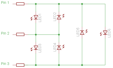
However, I also need to get the transistor in as well. And I don't want it getting switched on along with any of the LEDs. Well, lucky me. Turns out that with that constraint I can charlieplex a maximum of four LEDs and this transistor. Here's the circuit that I ended up with (click to enlarge):

Without transistor Q, LR anode can be connected to line2 and its cathode to com and only one current limiting resistor (on com pin) is necessary. With this configuration I tried designing in two resistors, but it seems three are required. Each resistor is half the value since two resistors are conducting whenever an LED is on.
The following table shows the I/O pin configuration necessary to switch on the different LEDs and transistor. 1 = output high, 0 = output low, Z = input mode
part on | line1 | com | line2To turn off all the devices just turn all pins into inputs. Yes, the gate of the MOSFET is floating when line2 is high-Z, so a pull-down resistor may be necessary.
--------+-------+-----+--------
LG | 1 | 0 | Z
LY | 0 | 1 | Z
LO | Z | 1 | 0
LR | 1 | Z | 0
Q | Z | Z | 1
Notes:
I actually didn't know the name of this technique when I read about it some two years ago in Microchip's 8-pin PIC Tips 'n Tricks literature. By the way, here's the latest Tips 'n Tricks. It's actually a compilation of all existing TnTs. Great resource.
Monday, December 28, 2009
When not to use a clamp meter
 Was just wondering whether my hardly-used Sanwa DCM 60L clamp meter would be able to measure the current draw of an incandescent lamp. I tried it out on a 60Watt bulb, and to my surprise the meter reading remained at 0.0A. Odd, I thought. I then tested a 100Watt. The meter budged by one count and read 0.1A. Obviously the meter was incorrect in the first case, since the bulb was shining brightly. And unless the lamp was way out of spec, the meter was wrong in the second case as well.
To find out the real deal, I decided to determine current using the Sanwa CD771 multimeter. I placed a 10-ohm, 5%, 1-Watt resistor in series with the bulb (the lamp socket, that is, in my test rig) via a terminal block onto which I screwed in the resistor leads and the wires to make a good and safe connection. The ohmmeter measured the actual resistance to be 9.5 ohms.
I would've wanted a smaller resistor value so that it would be insignificant compared to the lamps' filament resistance. Unfortunately I don't have any resistor smaller than 10 ohms and I don't have any other 10-ohm resistor (which I could connect in parallel). So I had to make do with this one resistor even if according to my calculations it would burn out if I used a 100-Watt lamp in the circuit: [(100W/220V)2]10Ω = 2.1Watts.
What's with the resistor anyway? I want to find out the actual current going through the circuit. To accomplish that I would measure the voltage drop across the resistor. It would then be trivial to compute for the current through the resistor and, because this is a series circuit, that would be the same current through the lamp as well.
The results are in the table below. Measured voltage of the mains at the time of testing was 232 Volts. This is the value used for calculations in the last column.
| Lamp Type | Clamp meter reading (without resistor) | Voltage Drop across Resistor (V) | Computed Current (A) | Computed Total Power Dissipation (W) |
| Philips Softone 60Watts | 0.0 | 2.59 | 0.27 | 62.6 |
| Philips Spotline R80 60Watts | 0.0 | 2.57 | 0.27 | 62.6 |
| Philips Superlux 100Watts | 0.1 | 4.31 | 0.45 | 104.4 |
As can be seen above, the lamps are in fact very close to their specified output and it was the clamp meter that was way, way off the mark. But why? I read the manual again and it turns out that at 50-60Hz the meter's accuracy is +/-(2% + 5 counts) and at 60-500Hz it's +/-(2.9% + 5 counts). These are for currents <200A.
Since the reading can be off by 5 digits (in this case that translates to +/- 0.5A), this clamp meter is absolutely useless for measuring currents less than 1A. Even for a current of 1A this meter will show anywhere from 0.4 to 1.5A. Thus the reading can be off from the true value by -60% to +50%. For 10A, reading will be in the range of 9.2 to 10.7A, which translates to -8% to +7% accuracy. Tolerable. In the 200A range, the meter reaches its highest accuracy of +/- 2 to 2.9% when measuring currents just below 200A. At over 100A the +/-0.5A (which is what the +/- 5 counts means in this range) becomes negligible.
So now I must remind myself that with this particular meter I have to take with a grain of salt any reading below 10A. Given the 220VAC mains voltage here, finding out the current draw of a load less than 2000W simply isn't worth checking with this meter.
Saturday, December 26, 2009
Twinkle, twinkle little bulbs, how I wonder how you're powered
Been meaning to find out the design of commercial Christmas lights control units. Obviously a microcontroller takes care of the various flashing patterns, frequency, fading in and out, etc. I was at a loss, however, at how they power the MCU--a low voltage DC device--and what they use to power the lamps--AC or DC.
Got the chance to do that when I fortuitously came across some old strings of lights that my brother had left here about a year or so ago. I didn't even know he had left them. I was clearing some stuff and stumbled upon them.
This particular set has three wires coming out of the control box. It was evident that one was a common and the two other were strings of bulbs. A momentary contact switch allows the user to cycle through the six or eight lighting/flashing patterns.
I was smiling when I saw two screws on the small control case. That meant I could actually open the thing up without cracking the case to bits. I would've been rather reluctant to ruin the plastic enclosure had it been glued shut.
I promptly opened the case and to my surprise the board contained very few parts. Take a look (click to see a larger version):


Seeing the four diodes immediately told me that the circuit uses a bridge rectifier. The electrolytic capacitor must be for filtering, I mused. And the two TO-92 parts just had to be transistors to switch the two lines of bulbs. The MCU is on the vertical daughterboard, the die sealed in a blob of black epoxy.
What intrigued me was how the MCU was being powered. At first I thought that the two resistors might be forming a voltage divider and feeding the MCU with a low voltage DC which is then filtered by the cap. But when I took the multimeter, traced the connections, and actually drew out the circuit, it turns out this simply was not so.

I now believe that the MCU has an integral shunt regulator or a voltage regulator of some sort which automatically delivers the required MCU voltage, probably 5V. The 180K resistor is necessary in order to drop practically all 200VDC across it (VACrms × √2 × 0.636 = VDC average). The 10uF capacitor filters the pulsating DC. Its 63V rating implies that voltage at the MCU's VDD pin is well below the raw rectified voltage of 200VDC (with a peak of >300V). That the resistor value is 180K means that average current going through is tiny--200V/180K = 1.1mA. The MCU has to be using a relatively low clock frequency and the load--the two transistors--have to be drawing a miniscule current.
Since I see no crystal, resonator, or resistor-capacitor to serve as clock, the MCU is probably using an internal oscillator. Stands to reason since this is a low-priced product. The board has provisions for 4 transistors and thus 4 branches of lights but only two are installed. Counting all the connections to the MCU including the provision for two more transistors, I surmise that this is an 8-pin type. Since the lighting pattern chosen by the user via the tactile switch is remembered even after the unit had been turned off, the MCU must be storing the value in nonvolatile memory, probably EEPROM.
Interestingly the 2-Mohm resistor is connected to the 220VAC line. The other end meanwhile goes directly to one of the MCU's pins. This must imply that the zero crossing of the AC wave is being sensed. Why would the circuit be doing that? It probably uses zero crossing for pulse width modulation timing purposes. Among the patterns available in this set of lights is a gradual fade in/out. Given the components, without a doubt PWM is being used to achieve this. I imagine that the PWM frequency is 120Hz--synchronized to the power line--while the duty cycle is varied from 100 to % (and back to 100%) when the lights are being dimmed and brought back to full brightness. Whenever a zero crossing is detected, the transistor is switched on. For how long depends on the duty cycle as determined by the firmware. How fast the duty cycle is incremented/decremented is variable--again as determined by firmware.
Since the load is being powered by full-wave rectified and unfiltered AC, the PWM system is analogous to AC phase control. Had this been an AC system, the MCU would, upon detection of zero crossing, begin timing. After a computed delay time, it would pulse the triac briefly to turn it on. The triac would then conduct until the next zero crossing upon which it automatically turns off and switches to high impedance state.
In this all-DC system, transistors are used for switching. Although I drew NPN BJTs in the above schematic, there is a good chance that MOSFETs are being used since they draw very little current. And as you may have noticed there are no current limiting resistors to the base of the transistors. I googled the printed part number "1225 A868" but couldn't find any useful information on it. What we do know is that these transistors are high voltage types since >300V peak will be across their output terminals.
Got the chance to do that when I fortuitously came across some old strings of lights that my brother had left here about a year or so ago. I didn't even know he had left them. I was clearing some stuff and stumbled upon them.
This particular set has three wires coming out of the control box. It was evident that one was a common and the two other were strings of bulbs. A momentary contact switch allows the user to cycle through the six or eight lighting/flashing patterns.
I was smiling when I saw two screws on the small control case. That meant I could actually open the thing up without cracking the case to bits. I would've been rather reluctant to ruin the plastic enclosure had it been glued shut.
I promptly opened the case and to my surprise the board contained very few parts. Take a look (click to see a larger version):


Seeing the four diodes immediately told me that the circuit uses a bridge rectifier. The electrolytic capacitor must be for filtering, I mused. And the two TO-92 parts just had to be transistors to switch the two lines of bulbs. The MCU is on the vertical daughterboard, the die sealed in a blob of black epoxy.
What intrigued me was how the MCU was being powered. At first I thought that the two resistors might be forming a voltage divider and feeding the MCU with a low voltage DC which is then filtered by the cap. But when I took the multimeter, traced the connections, and actually drew out the circuit, it turns out this simply was not so.

I now believe that the MCU has an integral shunt regulator or a voltage regulator of some sort which automatically delivers the required MCU voltage, probably 5V. The 180K resistor is necessary in order to drop practically all 200VDC across it (VACrms × √2 × 0.636 = VDC average). The 10uF capacitor filters the pulsating DC. Its 63V rating implies that voltage at the MCU's VDD pin is well below the raw rectified voltage of 200VDC (with a peak of >300V). That the resistor value is 180K means that average current going through is tiny--200V/180K = 1.1mA. The MCU has to be using a relatively low clock frequency and the load--the two transistors--have to be drawing a miniscule current.
Since I see no crystal, resonator, or resistor-capacitor to serve as clock, the MCU is probably using an internal oscillator. Stands to reason since this is a low-priced product. The board has provisions for 4 transistors and thus 4 branches of lights but only two are installed. Counting all the connections to the MCU including the provision for two more transistors, I surmise that this is an 8-pin type. Since the lighting pattern chosen by the user via the tactile switch is remembered even after the unit had been turned off, the MCU must be storing the value in nonvolatile memory, probably EEPROM.
Interestingly the 2-Mohm resistor is connected to the 220VAC line. The other end meanwhile goes directly to one of the MCU's pins. This must imply that the zero crossing of the AC wave is being sensed. Why would the circuit be doing that? It probably uses zero crossing for pulse width modulation timing purposes. Among the patterns available in this set of lights is a gradual fade in/out. Given the components, without a doubt PWM is being used to achieve this. I imagine that the PWM frequency is 120Hz--synchronized to the power line--while the duty cycle is varied from 100 to % (and back to 100%) when the lights are being dimmed and brought back to full brightness. Whenever a zero crossing is detected, the transistor is switched on. For how long depends on the duty cycle as determined by the firmware. How fast the duty cycle is incremented/decremented is variable--again as determined by firmware.
Since the load is being powered by full-wave rectified and unfiltered AC, the PWM system is analogous to AC phase control. Had this been an AC system, the MCU would, upon detection of zero crossing, begin timing. After a computed delay time, it would pulse the triac briefly to turn it on. The triac would then conduct until the next zero crossing upon which it automatically turns off and switches to high impedance state.
In this all-DC system, transistors are used for switching. Although I drew NPN BJTs in the above schematic, there is a good chance that MOSFETs are being used since they draw very little current. And as you may have noticed there are no current limiting resistors to the base of the transistors. I googled the printed part number "1225 A868" but couldn't find any useful information on it. What we do know is that these transistors are high voltage types since >300V peak will be across their output terminals.
Saturday, December 19, 2009
ATX in AT's clothing
I was going to use a very old AT power supply and convert it into a bench power supply, the reason being that it has a much larger case than an ATX which means there would be ample space for the seven binding posts I intend to install (five voltages and two ground). Moreover, it has an integral AC power switch right on the case--something you no longer get in current power supplies (and in some AT's the switch is not on the case but on the front panel of the computer). So this enclosure is perfect.
Alas, a check of the voltage outputs revealed that while the +5VDC line was fine, its +12VDC was only delivering 10.8V even when two hard drives were plugged in and whirring away. This was rather disappointing since a 10% deviation is simply unacceptable. But I really want this enclosure.
To cut to the chase I found an ATX power supply from a discarded Pentium 3 computer which showed output (positive) voltages within 5% of their stated values. After mulling it over I decided to disembowel the AT and transplant the ATX board into it.
Testing the ATX I discovered that while even without a load the PS starts (fan spins) and outputs were live, without any load the outputs were not too good: +5.25VDC and +11.5VDC. These two voltages are the most important to me so they're the ones I use as benchmark. I further discovered that loading the 12VDC line did not improve its output. But loading the 5VDC line not only pushed that output down toward 5.0VDC, but also pulled up the 12VDC line toward 12.0V.
My main reference for this project is How to Convert a Computer ATX Power Supply to a Lab Power Supply. In that article it advises using a power resistor to load the output. I thought, Why waste all that good power? Why not put it to some use? As in lighting up a bank of LEDs. I initially thought of using white LEDs that would be configured into some sort of a lamp to illuminate whatever circuit the PS was powering. However, I decided to illuminate the interior of the enclosure instead, using colored LEDs to bathe the components inside in theatrical lighting.
The AT has a 110/220VAC switch. Right above that is the socket into which the computer monitor's power cable is plugged. This area would be perfect and large enough for a small prototyping board with all the LEDs mounted on it. So I removed both the switch and socket. I cut a board down to a size that would fit that space. I then populated it with a total of 8 red and 10 blue LEDs. Supply is 5VDC and resistors were chosen such that current is about 15mA per branch. Measured forward voltage of the red LEDs were 1.8 and so two reds are in series per branch with a 100-ohm resistor as current limiter. Blues have a forward voltage of 3.0V and so there's only one LED per branch in line a 150-ohm resistor. There are 14 branches and so total current is around 210mA, for a total power dissipation of around 1000mW. Test shows that with this load, output voltages are as follows:
The green and a black wire are connected to a switch at the back. When green is not connected to ground PS is virtually off including the cooling fan. When green wire is grounded PS supplies power to the outputs. The AC power switch has to be closed of course. Purple and gray wires ("standby" and "power-good", respectively) are not used and not connected to anything.
Here's the ATX board and its fan already installed in the AT enclosure. The connectors to the motherboard and drives have all been snipped off and I've bundled and temporarily taped the wires by color (voltage). The bunch of red-black-yellow wires on the right is for the LEDs. I initially was going to use the +12V (yellow) but then as I said above tests showed that using it does not contribute to +12V output regulation. This yellow wire eventually joined its siblings.

Here it is after the case cover had been drilled and the binding posts installed. I couldn't find any other colors besides red and black so I used red binding posts for the negative voltages as well. Notice there are two posts for ground.

Back view showing the AC power switch and the PS-ON switch. The reason for the latter's location is that there already was a 1/8" hole on that spot. I just made it larger. The "AMAX" plastic sticker nameplate is from the ATX. You can see that the power supply was made in 2000. The neat thing about this PS is that it actually lists the wire color codes.

A look inside the connections to the binding posts. All wires were terminated with ring lugs. Even if the nuts come loose the wires won't fall onto the board and possibly cause disaster.

A view from the fan side. You can see the rectangular holes where the the monitor power socket and 220/110V selector switch once were. Because the copper side of the prototyping board will be exposed and accessible through these holes, I mounted an aluminum sheet to seal them. The sheet is sandwiched between the casing the two standoffs for the board.

The prototyping board is clearly visible. The top two rows are red LEDs. The rest are blue. I ran out of diffused epoxy blue LEDs so most of them are the clear type.


And the LEDs are shining!

The following were taken in complete darkness. Even with 18 LEDs the total output is nowhere close to bright.


Alas, a check of the voltage outputs revealed that while the +5VDC line was fine, its +12VDC was only delivering 10.8V even when two hard drives were plugged in and whirring away. This was rather disappointing since a 10% deviation is simply unacceptable. But I really want this enclosure.
To cut to the chase I found an ATX power supply from a discarded Pentium 3 computer which showed output (positive) voltages within 5% of their stated values. After mulling it over I decided to disembowel the AT and transplant the ATX board into it.
Testing the ATX I discovered that while even without a load the PS starts (fan spins) and outputs were live, without any load the outputs were not too good: +5.25VDC and +11.5VDC. These two voltages are the most important to me so they're the ones I use as benchmark. I further discovered that loading the 12VDC line did not improve its output. But loading the 5VDC line not only pushed that output down toward 5.0VDC, but also pulled up the 12VDC line toward 12.0V.
My main reference for this project is How to Convert a Computer ATX Power Supply to a Lab Power Supply. In that article it advises using a power resistor to load the output. I thought, Why waste all that good power? Why not put it to some use? As in lighting up a bank of LEDs. I initially thought of using white LEDs that would be configured into some sort of a lamp to illuminate whatever circuit the PS was powering. However, I decided to illuminate the interior of the enclosure instead, using colored LEDs to bathe the components inside in theatrical lighting.
The AT has a 110/220VAC switch. Right above that is the socket into which the computer monitor's power cable is plugged. This area would be perfect and large enough for a small prototyping board with all the LEDs mounted on it. So I removed both the switch and socket. I cut a board down to a size that would fit that space. I then populated it with a total of 8 red and 10 blue LEDs. Supply is 5VDC and resistors were chosen such that current is about 15mA per branch. Measured forward voltage of the red LEDs were 1.8 and so two reds are in series per branch with a 100-ohm resistor as current limiter. Blues have a forward voltage of 3.0V and so there's only one LED per branch in line a 150-ohm resistor. There are 14 branches and so total current is around 210mA, for a total power dissipation of around 1000mW. Test shows that with this load, output voltages are as follows:
| Ideal output (volts) | Actual output (volts) |
| -12 | -10.76 |
| -5 | -4.77 |
| +3.3 | +3.32 |
| +5 | +5.17 |
| +12 | +11.96 |
The green and a black wire are connected to a switch at the back. When green is not connected to ground PS is virtually off including the cooling fan. When green wire is grounded PS supplies power to the outputs. The AC power switch has to be closed of course. Purple and gray wires ("standby" and "power-good", respectively) are not used and not connected to anything.
Here's the ATX board and its fan already installed in the AT enclosure. The connectors to the motherboard and drives have all been snipped off and I've bundled and temporarily taped the wires by color (voltage). The bunch of red-black-yellow wires on the right is for the LEDs. I initially was going to use the +12V (yellow) but then as I said above tests showed that using it does not contribute to +12V output regulation. This yellow wire eventually joined its siblings.

Here it is after the case cover had been drilled and the binding posts installed. I couldn't find any other colors besides red and black so I used red binding posts for the negative voltages as well. Notice there are two posts for ground.

Back view showing the AC power switch and the PS-ON switch. The reason for the latter's location is that there already was a 1/8" hole on that spot. I just made it larger. The "AMAX" plastic sticker nameplate is from the ATX. You can see that the power supply was made in 2000. The neat thing about this PS is that it actually lists the wire color codes.

A look inside the connections to the binding posts. All wires were terminated with ring lugs. Even if the nuts come loose the wires won't fall onto the board and possibly cause disaster.

A view from the fan side. You can see the rectangular holes where the the monitor power socket and 220/110V selector switch once were. Because the copper side of the prototyping board will be exposed and accessible through these holes, I mounted an aluminum sheet to seal them. The sheet is sandwiched between the casing the two standoffs for the board.

The prototyping board is clearly visible. The top two rows are red LEDs. The rest are blue. I ran out of diffused epoxy blue LEDs so most of them are the clear type.


And the LEDs are shining!

The following were taken in complete darkness. Even with 18 LEDs the total output is nowhere close to bright.


Subscribe to:
Posts (Atom)