Sunday, September 12, 2010

Pantry light switch using a PIR module

Practically all the dry goods in our kitchen are stored in the pantry and we access this room several times a day. My bugbear has been that everyone who uses it, including myself, forgets to turn off the light rather frequently. Something about this tiny room that makes people run in and out less than a minute later and forget to flip the switch. Must the duration of stay inside. Or maybe not, since I also do fail to turn the garage storeroom lights off even if I've been in there for ten minutes. Yeah, must be the genes.

Been meaning to install a motion detector to address this problem but couldn't find a readily available PIR in the market. Went to a home depot months ago to buy a consumer security gadget that employed PIR and was going to just hack it. Problem is that when I asked them to test if it's working the dang model didn't. Not a single unit of those tried! What the bleep indeed.

Well, fortunately I found an online supplier who had reasonable prices. The module is China-made obviously, but right now I'll take anything over nothing. For details and specs of the passive infrared (PIR) module refer to my previous blog entry.

I could've used the module without employing a microcontroller. A transistor and a relay would've been sufficient to switch on the pantry's compact fluorescent lamp (CFL). But that's crude and not at  all very user friendly. What happens when the person is still inside and isn't detected by the PIR? Darkness descends without warning. Therefore, there is a need to provide an alert of some sort that it'll be lights out in a while.

I would've wanted a visual warning, specifically a PWM controlled lamp that gradually dims. The decreasing light level would be a gentle way of informing the user. But such a circuit is more complicated and I certainly can't dim a CFL. LED high-lumen lighting would be nice, but cost is prohibitive and the drive circuitry complex.

So I settled for an audible alert, giving a graduated level of warning as the moment of lamp switch-off approaches. I arbitrarily set the start of warning five seconds before switch-off, with a 10ms beep every second for four seconds. On the last second, a 10ms beep is issued every 200ms for a total of five beeps. The beeps are generated by a small sonalert buzzer but at 10ms they're so short that they sound more like clicks than beeps. My design criterion on this is that the sound level and type should be informative but unobstrusive to those outside the room, so the clicks are on the money.

The MCU's job is simply to monitor the PIR module output and switch the CFL accordingly. When PIR output goes high the MCU immediately switches on the CFL, and when it goes low the MCU starts issuing the alert sequence, after which it turns off the lamp.

However, since this particular module has an initialization ritual it goes through upon power up, the MCU must also be programmed to disregard the output during this period. Well, the MCU doesn't really have to, but for now I've decided that it should ignore the two PIR output high during initialization since energy is wasted when the CFL on. On the other hand, there is some utility to providing feedback that the PIR is in initialization mode. This can be implemented using the buzzer. A distinct pattern of beeps can be continuously emitted during this period.

In anticipation of future PIR module malfunction and of those times when the user would want to keep the light on continuously--i.e., override the sensor--I designed the circuit with a switch to allow the user to turn off auto mode. When in manual mode the CFL will be on regardless of PIR output. The manual override is a surface mount rocker switch rated at 10A @250VAC. Only a feeble current (about half a milliamp DC) will be running through so it'll be dry switching. I'm not worried.

Since the MCU won't be doing much at all and will only need a small amount of code, I decided to use a baseline PIC, i.e., a model from the 10F series. The smallest (in Flash memory) chip I have in stock is the PIC10F202. It has four I/O pins which is exactly the number of pins I need.

Powering the CFL is via a miniature socketed relay with a 12VDC coil. The Telemecanique RXM2AB2JD is a DPDT switch with contacts rated at 12A @250VAC. As a bonus it has a green LED indicator which is on when the coil is energized. It even has a button which the user can push to momentarily close/open the NO/NC contacts and a mechanical lever to latch them. Love its smart look as well. Thumbs up to this model.

To serve as a troubleshooting aid I've added an LED which is switched on by a transistor whenever PIR output is high. The MOSFET is controlled directly by the PIR.

Powering the control circuitry is a generic wall cube which has no markings on it. Thankfully this unit isn't one of those whose casing is glued together. It has two screws which allows it to be opened up. As the schematic below shows it has a transformer, bridge rectifier made up of four diodes (can't make out the last digit of any of the 1N400x) and a filter capacitor. Output of the adapter is 19VDC, no load.

A LM7812 provides a regulated 12VDC. Although not strictly necessary given the current draw of the circuit, a clip-on anodized aluminum heat sink has been installed on this TO-220 as a precaution.  To preclude having too high a voltage headroom, the 78L05 regulator's input is drawn from the output of the LM7812. This reduces the dissipation of the 5VDC regulator.

Here are the schematic diagrams and legend to the reference designations.


The 10F series of PICs has no interrupt capability and only a 2 level stack for subroutine calls. Pretty spartan indeed, but quite adequate for simple undemanding circuit requirements like this one. I've used the 10F202 for a number of circuits but something I've not learned or already forgotten manage to trip me up. Pretty vexing really. While prototyping I used GP2 as the I/O for the sonalert buzzer. Well, it didn't work! I went over the firmware and it looked good. Took me a long time poring over the datasheet for me to finally discover that GP2 is by default an input pin even if the TRISGPIO2 bit has been correctly set as output. The fact is the TRISIO register has the lowest priority in determining the status of this pin. OSCCAL register FOSC4 bit has the highest priority followed by OPTION register TOCS bit. No problem with FOSC4 since it is upon power up set to zero which means it hands off this pin to other functions. The problem lies with TOCS. It's set to 1 upon any type of reset including power on. And that means the pin is in high impedance mode waiting for a signal. With TOCS set, Timer0 is in counter mode and increments upon a level change (edge trigger) on the GP2 pin. So in order to use this pin as a general I/O TOCS has to be cleared. The 10F202 is practically the most basic MCU in Microchip's line but I have yet to master it.

In the end I moved the buzzer to GP1 and used GP2 as an input to sense the status of the auto/manual switch. GP3 is input-only and is used to monitor PIR output. Note that the PIR module works at 3.3VDC and its output high can only reach a maximum of this value. With a VDD of 5V a Schmitt trigger input on the MCU won't be able to detect the PIR high since the minimum requirement for a level high is 80% of VDD, or 4V. Fortunately, when the 10F202 pins are configured as general purpose inputs they are all TTL which has a minimum requirement of only 2.0V to be considered as high. Not so in other cases. For instance when TOCS bit = 1, GP2 becomes a Schmitt trigger input for Timer0 counter. Thus, if we feed the PIR output to this pin, Timer0 would never increment. What the PIR outputs as high would be considered a valid high only if MCU VDD drops to 4.1VDC or less.

Firmware consists mainly of a series of polling loops. PIR output is continually monitored while the manual switch is monitored continually only after PIR initialization is complete. When switch SW1 is sensed to be in manual and as long as it is in manual position, PIR is no longer monitored. When SW1 is flipped back to auto position then PIR monitoring resumes.

In auto mode and after PIR initialization has been detected to be over, when PIR output goes high, Q2 is immediately turned on which then switches REL on and hence LOAD. When PIR output goes low, the pattern of beeps (as described above) is issued. Five seconds later LOAD is switched off. If PIR output goes high during this five-second waiting time, the alerts stop and firmware exits the alert routine.

When user switches from manual to auto mode, firmware checks PIR output to determine whether LOAD will be turned off or not. PIR will almost certainly be high since SW1 is located inside the pantry and in an area right under the PIR, thus making sure the user will be detected while operating the switch. Be that as it may, if PIR output is low then LOAD is turned off, otherwise it is kept on.

Currently, there is no routine to issue an audible alert informing the user that the PIR is initializing. There should be. That will probably come in a firmware upgrade.

The actual firmware installed is provided below. It's written in MPLAB assembly. Uses only 87 words of flash and 4 bytes of RAM. Watch out! I use homebrew macros and defines throughout. Blogspot truncates any text that extends beyond the margins so if you want to read the code and comments I suggest copying and pasting into a word processor. Or paste it in MPLAB, copy and paste the macros and defines from the above link as well, build it, and read the disassembly listing or "program memory" listing if you're not a huge fan of my macros. Shame on you if you aren't!


; ********************************************
; Passive Infrared Motion Detector for home panty
; September 2010
; 
; see "PIR sensor.dwg" for schematic
; *********************************************

 processor 10F202
 #include p10F202.inc
 #include et.inc

 __config _MCLRE_OFF & _CP_OFF & _WDT_ON
 
 cblock 0x08
CENTISECS    ; number of centiseconds for time delay
ICOUNTER    ; counter for iterations
COUNTER:2    ; counters for delays 
 endc
 
 #define  buz  GPIO,0   ; sonalert buzzer
 #define  load GPIO,1   ; switches MOSFET which switches 12VDC relay which switches 220VAC CFL
 #define  sw  GPIO,2   ; mode switch: high = manual (load is continuously on), low = auto (motion detect)
 #define  pir  GPIO,3   ; PIR output, high = motion detected, low = no motion detected
 
 org  0x0
 
 movwf OSCCAL      ; load clock calibration 
 goto initialize
 
; =======================================================================================
; subroutines
;
; 10F202 can only call subroutines if they are located in first 256 memory locations
; =======================================================================================

; ---------------------------------------------------------------------------------
; Time delay that's user dependent 
; Place number of centiseconds of delay in register CENTISECS before calling this routine
DelayCentisec:
 movlf .164, COUNTER
 movlf .20, COUNTER+1
delay_loop 
 decfsz COUNTER,f
 goto delay_loop
 movlf .164, COUNTER
 decfsz COUNTER+1,f
 goto delay_loop
 clrwdt
 movlf .20, COUNTER+1
 decfsz CENTISECS,f
 goto delay_loop
 retlw 0 
; ---------------------------------------------------------------------------------

; ---------------------------------------------------------------------------------
; one centisec beep
Beep:
 bsf  buz
 movlf .1, CENTISECS
 call DelayCentisec
 bcf  buz
 retlw 0
; ---------------------------------------------------------------------------------


; =======================================================================================
; main program
; =======================================================================================

; ---------------------------------------------------------------------------------
initialize:
 clrf GPIO
 movlw b'11011111'    ; TOCS bit must be 0 else GP2 will be an input pin; prescaler is assigned to WDT; prescale = 1:2 
 option
 movlw b'1100'     ; GPIO 0 and 1 are assigned as output, GP2 is input, GP3 is by default an input only pin
 tris GPIO

; do nothing for about half a second (50 centisec) to give PIR time to initialize and bring its output high
 movlf .50, CENTISECS
 call DelayCentisec

; PIR initializes by outputting high twice over a minute or two
; wait until the second falling edge is detected; thereafter any edges detected will be due to normal operation of motion detection 

; wait for first PIR falling edge
init_pir_loop1
 clrwdt
 dnxtrue pir
 goto init_pir_loop1

; wait for PIR rising edge 
init_pir_loop2 
 clrwdt
 dnxfalse pir
 goto init_pir_loop2
 
; wait for second PIR falling edge--signals the end of PIR initialization 
init_pir_loop3
 clrwdt
 dnxtrue pir
 goto init_pir_loop3
 
; ---------------------------------------------------------------------------------

; ---------------------------------------------------------------------------------
main:
 ; wait for PIR rising edge--which signals that motion has been detected
 ; check mode sw status 
 clrwdt
 dnxtrue sw     
 goto manual
 dnxfalse pir
 goto main

main_motion_true
 bsf  load    ; PIR output is high so turn load on 
 
main_loop1
 ; wait until no motion is detected--until PIR output goes low
 ; check mode sw status
 clrwdt
 dnxtrue sw      
 goto manual
 dnxtrue pir
 goto main_loop1

; PIR output is now low 
; give user 5 seconds to activate motion sensor before turning off load
; begin issuing 10ms beep every second for four seconds to alert user that motion is no longer detected
; check PIR output every second; if it goes high (motion is detected) then exit and go to main_loop1 
; check mode sw status every second; if sw level goes high then go to manual mode routine
main_motion_false
 movlf .4, ICOUNTER
main_beep_loop0
 call Beep
 movlf .99, CENTISECS
 call DelayCentisec
 dnxtrue sw      
 goto manual
 dnxtrue pir     
 goto main_loop1
 decfsz ICOUNTER,f
 goto main_beep_loop0

; for the last second issue a 10ms-beep every 200ms
; check PIR output every second; if it goes high (motion is detected) then exit and go to main_loop1 
; check mode sw status every second; if sw level goes high then go to manual mode routine
 movlf .5, ICOUNTER
main_lastsec_beep_loop0 
 call  Beep
 movlf .19, CENTISECS
 call DelayCentisec
 dnxtrue sw     
 goto manual
 dnxtrue pir
 goto main_loop1
 decfsz ICOUNTER,f
 goto main_lastsec_beep_loop0

; if PIR output remains low then turn load off
; go to main whether PIR output is low or high
 dnxfalse pir
 bcf  load
 goto main  


; manual mode routine
; if sw level is high then turn load on 
; if sw level is low and PIR output is low then turn off load
; if sw level is low and PIR output is high then keep load on
; when sw level is low then go to main
manual:
 bsf  load
manual_loop1
 dnxfalse sw
 goto manual_loop2
 clrwdt
 goto manual_loop1
manual_loop2
 dnxfalse pir
 bcf  load
 goto main


 end

; ----------------------------------------------------------------------------------


The Installation

I need to have control over the area covered/monitored by the PIR sensor but don't have the resources nor the perseverance to build a metal articulated aiming gizmo. Scrounged around and found a round tea can made of cardboard whose slip-on lid could be rotated while it was on. That provides one axis of rotation to aim the the sensor. I could easily bore a hole on the side of the canister and fasten the module with the Fresnel lens sticking out. The lid would then be screwed onto a block of wood which in turn would be bolted to the side panel of the top shelf. If I use just one bolt I can swivel the block. That's the second axis of rotation which would be at right angles to the first. Two planes of swivel is sufficient to aim the sensor practically anywhere.

Here are photos of the installation. The first shows the can with the module already in place. I wish I didn't have to glue it to the can but my brain was out of options. The can is actually red. I covered with white paper since the shelves are all white. I don't want it out more than it already will be and calling attention to it. The three wires lead to the circuit board where all the other components are.


The lid of the canister is shown fastened to a scrap piece of wood which is epoxied (the black goo) to another piece perpendicular to the former. The latter is bolted to the shelf side panel. The outlet on the pantry wall is newly installed just for this circuit. The thicker SPT cable is 220VAC power line and the smaller gauge SPT leads from the relay to the CFL. The translucent plastic box contains the circuit board and relay


In the bottom picture, the circuit is powered and operational. There's the wall wart plugged in with its (newly installed) red and black speaker cable leading to the circuit board inside the plastic box. The wire from the black plug leads to the relay. The white SPT wire along the bottom of the photo leads to the auto-manual switch located several shelves below. You can see I just taped it along the edge of the shelf.


In this last photo I am at ground level pointing the camera up. CFL is mounted on the ceiling less than a meter from the module.

PIR sensor module


Recently bought a couple of passive infrared (PIR) modules. The seller lists the part number as DC-SS015, although I can't be certain that this indeed is true. Unfortunately the seller could not provide any datasheet. It may in fact be a SS015 since the pin designations for the headers are the same as those on a datasheet for the DC-SS015 (see below).

As far as I can tell there are only two ICs on this module. The SOIC-16 (left of center in the photo) does not have any markings. It could be a BISS001 clone. The (4-pin) SOT-89 (lower right in photo) has ""7533-1" printed on it. I googled and this may be a Holtek 3.3V LDO voltage regulator.

The board measures 33mm x 25mm and is marked "Rev1.1." The fresnel lens is hot glued to the board and for now I have not dared remove it for fear of misaligning it.


The black circular thingie beneath the board is just a 35mm film canister to the prop the board up. Needed to  keep it level with the table while taking the picture given the domed fresnel lens on the other side.

 Here are screenshots of the pertinent pages from a datasheet I found for the DC-SS015 some time ago. I can no longer find the link for the pdf file by Sure Electronics


The position on the board and designation of the header pins of the module match those shown on the datasheet.  The 3-pin header at the bottom center of the board (as per the photo above) are for power and output. Left pin (silkscreened "SW") is ground, center pin (marked "OUT") is output, right pin is Vcc.

The 3-pin header on the upper left corner has a jumper to select between single trigger and re-triggerable modes. The topmost pin is labeled "H" on the module, while the lowermost pin is labeled "L." With the jumper plugged into the two top pins (H and common) the circuit becomes retriggerable, that is, any motion detected will reset the output high holding period to whatever the user has set it to. With the jumper plugged into the lower two pins (common and L) only the initial motion detected is counted and any further trigger will be ignored until the output-high holding period has elapsed. In other words, in single trigger mode assuming PIR module output is initially low, the time between motion is detected (output goes high) and output goes low is constant.

The output-high holding period (for both trigger modes) is user adjustable and is set via a 1Mohm trimmer resistor. That's the orange part on the upper right corner of the board. I've played around with it and the range is from almost zero to 16.75 seconds. The module arrived with the trimmer set at center, which had a measured time of between 9 and 10 seconds.

I measured the current draw using a Fluke 87V with its min-max feature turned on. Input voltage was measured at 5.18VDC (using an ATX power supply) and load was a 2N7000 MOSFET with its gate directly connected to the PIR output (no limiting resistor). Minimum current recorded was 37µA while maximum was 98µA. As you can read from the datasheet, quiescent current is specified at 50µA.

With the module powered from the same supply as above, output voltage was measured with a Fluke 8842A and for this test module, without any load, low was less than 0.03mV and high = 3.31V. 

The module has a long initialization time. After powering up output will go high for several seconds, go low for a shorter period of time, high again for several seconds, and then back low. Thereafter, it will be not triggerable for several more seconds. The period for this set up doesn't seem to be fixed, but the whole thing takes about a minute.

This unit is able to detect human movement to 4 meters, but sensitivity at that distance is fair at best. Seems to perform well enough within two meters. Angular coverage is apparently greater horizontally (as per board orientation in the photos above) than vertically. Difficult to give precise values, but 90 degrees would be a ballpark figure.

I've already used one of the modules in a circuit that automatically switches a compact fluorescent lamp inside a pantry. I'll probably do a blog on that soon. 

Finally, for a tutorial on PIR devices check out ladyada.

Saturday, September 4, 2010

Adjustable power supply with automatic transformer tap select


I'm currently designing and testing a 1-amp power supply based on the good old LM317 voltage regulator. I'd like it to be able to supply a voltage from its minimum of 1.25 V all the way to about 30 V. That's within its specs so no problem with that range. However, one problem is the power dissipation of the 317 which is given by:

\[
P_D = I_{VR} ( V_{IN} - V_{O})
\]

where
$P_D$ = power dissipation, in watts
$I_{VR}$ = current through the voltage regulator, mostly the load current, in amperes
$V_{IN}$ = input voltage, in volts
$V_{O}$ = output voltage, in volts

The higher the difference between input and output voltage the greater the power loss in the 317. If we use a single input voltage it would have to be at least 33VDC, more likely >35V to factor in capacitor ripple voltage. With an input of 35V and an output of, say, 5VDC headroom would be 30V. If the load were drawing 100mA it would dissipate 5V x 0.1A = 0.5W while the 317 would be wasting 30V x 0.1A = 3W! Without a heatsink and given the thermal resistance of a TO-220 package of around 65°C/W, the junction temperature would well exceed its 125°C maximum. Of course the 317 will probably shut down before reaching that temperature, or it might fry if the thermal overload protection circuitry somehow fails.Not that we wouldn't install a heatsink. It's indispensable for a 1000-mA supply since even with a constant headroom of 3V (minimum required), the regulator would still be dissipating 3W at a current draw of 1A. In fact my calculations show that on top a heat sink with a thermal resistance of <= 10°C/W, I'll still need a cooling fan given the headroom that my design has.

Heatsinking cannot be overemphasized in this design since with all else constant $V_{O}$ changes with junction temperature. If you check the graphs of any LM317 datasheet you will find that load regulation, adjustment current, and reference voltage are all temperature dependent. Therefore, keeping the 317 temperature as constant as possible is paramount for a good constant voltage output with a varying load.

So there are several reasons for limiting voltage headroom. And one way to do so is to use a multitap transformer and feed the 317 with a voltage that depends on its output. The greater the output voltage the higher the voltage we input to the regulator. A control circuit monitors $V_O$ and selects the appropriate transformer tap via electromagnetic relays.

Unfortunately, for this design I couldn't find a multiple tap transformer (with four or five outputs) whose maximum voltage output is 30 or so volts RMS. The best I could find is a 14-0-14 volt center-tapped, which is equivalent to a 0-14-28. With only two output voltages only one relay is necessary. The idea is to switch to 28VAC when $V_O$ rises above the middle value of around 12VDC and to switch back to 14VAC when it falls below this. A hysteresis band will be necessary to prevent relay "chatter" when crossing the switchover voltage.

In my first design I powered the $V_O$ monitoring circuit from the same transformer. But it turns out that because the secondary windings are not isolated from one another the voltages go haywire when the two taps are used simultaneously--by the 317 and the monitoring circuit. So I've had to use a second transformer, with 12VAC output, to drive the relay and power the ICs that check $V_{O}$.

The monitoring circuit consists simply of a comparator with hysteresis wired in using two positive feedback resistors. I've decided to switch the relay when $V_{O}$ is around 13VDC. I will definitely use $V_{O}$ = 12VDC so I don't want it switching at that level. And I can't change taps at a much higher voltage since there might not be enough headroom for the regulator when current draw goes above 500mA. So I've pegged the trip comparator trip voltage between 13 and 14VDC.

To determine the resistor values, upper and lower trip voltages, and the hysteresis band, I needed formulas. Textbooks have not been of any help. They do have the equations but they're for op amps using bipolar power supplies. I'm keeping to single-supply op amps and those equations simply don't work. I've tried them and results don't match with measured values. Luckily Microchip has the holy grail in their literature.

From the Microchip MCP6541 datasheet we have the following equations to determine the trip voltages given positive feedback.

\[
V_{TLH} = V_{REF}\left ( 1 + \frac{ R_{F1}}{R_{F2}} \right )  - V_{OL} \left ( \frac{R_{F1}}{R_{F2}} \right)
\]

\[
V_{THL} = V_{REF}\left ( 1 + \frac{ R_{F1}}{R_{F2}} \right )  - V_{OH} \left ( \frac{R_{F1}}{R_{F2}} \right)
\]

where
$V_{TLH}$ = trip voltage when voltage at the noninverting input is going from low to high, in volts
$V_{THL}$ = trip voltage when voltage at the noninverting input is going from high to low, in volts
$V_{REF}$ = reference voltage, i.e., voltage at the comparator's inverting input, in volts
$V_{OL}$ = comparator low level output voltag, in volts
$V_{OH}$ = comparator high level output voltage, in volts
${R_{F1}}$, ${R_{F2}}$ = positive feedback resistances, in ohms

If output of the comparator is only very lightly loaded then $V_{OL}$ is only a few millivolts above ground. Moreover, ${R_{F1}}/{R_{F2}}$ is very small. Thus $V_{OL}  ({R_{F1}}/{R_{F2}})$ is practically zero. $V_{TLH}$ then reduces to:

\[
V_{TLH} = V_{REF}\left ( 1 + \frac{ R_{F1}}{R_{F2}} \right )
\]

It follows then that

\[
V_{THL} = V_{TLH} - V_{OH} \left ( \frac{R_{F1}}{R_{F2}} \right)
\]

With a very lightly loaded comparator output, $V_{OH}$ is for all practical purposes equal to the comparator's supply voltage $V_{DD}$.

Upper and lower trip voltages in terms of $V_O$ are obtained as follows:

\[
V_{TLH}' = V_{TLH} \left ( \frac {R_{VD1}+R_{VD2}} {R_{VD2}} \right)
\]

\[
V_{THL}' = V_{THL} \left ( \frac {R_{VD1}+R_{VD2}} {R_{VD2}} \right)
\]


Referring to the schematic above, the comparator's reference voltage is derived from a voltage divider and computed as follows:

\[
V_{REF} = V_{DD} \left ( \frac {R_{REF2}}{R_{REF1} + R_{REF2}} \right)
\]

where
$R_{REF1}$ and $R_{REF2}$ are the voltage divider resistor values, in ohms

The LM317 output voltage $V_O$ is to be monitored by the comparator. But because this swings from 1.25 to around 30VDC, while the comparator maximum input voltage is $V_{DD}$ = 5VDC, we need to "step down" the voltage sensed by the comparator by using a voltage divider. $ R_{VD1}$ and $R_{VD2}$ are chosen such that when $V_O$ is at its maximum then voltage divider output is equal to the comparator $V_{DD}$. Voltage divider output is given by:

\[
V_O \left ( \frac {R_{VD2}}{R_{VD1}+R_{VD2}} \right)
\]

The presence of the feedback circuit in the comparator necessitates a low impedance source. The voltage divider formed by $R_{VD1}$ and $R_{VD2}$ does not meet this requirement. Hence a unity gain buffer is necessary.

I initially used a MC33171 op amp for the comparator and a LM310 voltage follower as the buffer. Instead of having two ICs I want to use a dual single supply op amp IC with a $V_{CC}$ of > 12VDC but unfortunately I don't have any at hand. But I do have tons of Microchip single, dual, and quad op amps. I picked the MCP6282 for its rail-to-rail input and output and its good slew rate. $R_{VD1}$ and $R_{VD2}$ were chosen such that the voltage divider's maximum output is 5VDC.

Resistors, $V_{DD}$, and $V_{OH}$ of the breadboarded prototype were measured using a Fluke 8842A and their values were plugged into the equations above. $V_{TLH}'$ and $V_{THL}'$ were measured with the multimeter probes connected to $V_O$ and ground, and gradually turning the potentiometer. Theoretical and empirical results are within less than 0.25% of each other! That certainly blew my mind.


While designing this power supply I used an old malfunctioning ATX power supply 12VDC brushless motor cooling fan as a load since I could turn $V_O$ up and down and have some visual feedback on how it's affecting the load. And I could afford to ruin it should it burn up when I turned $V_O$ all the way up. Turns out choosing this fan was fortuitous because I discovered something totally unexpected. Without any load the comparator circuit worked fine and, depending on the values of the various resistors, there was some 1.5 to 2V ($V_O$) hysteresis band. But when the fan was powered hysteresis was lost and relay chatter was prominent when the trip voltage level was being crossed. I found out what was happening when I hooked up an oscilloscope to check $V_O$. It showed the fan was introducing positive and negative pulses (see oscilloscope screenshots below). And the comparator circuit was merely following what it's suppose to do--tripping (and being tripped up) when those pulses were present, as the difference between the peak positive and negative values exceeded the hysteresis band set by $R_{F1}$ and $R_{F2}$.

So I added a low pass filter section whose cutoff frequency can be computed as follows:

\[
f_c = \frac{1}{2\pi R_{LPF}C_{LPF}}
\]

where
$f_c$ = filter cutoff frequency, in hertz
$R_{LPF}$ = filter resistor value, in ohms
$C_{LPF}$ = filter capacitor value, in farads

This circuit filters out any transients occurring in $V_O$. With the LPF circuit in place oscilloscope reading of the unity gain buffer output was devoid of the noise pulses introduced by the fan.

I also used a new brushless DC fan as a load. Apparently even brand new fans also introduce spikes into $V_O$ although it seems their amplitude is not as high as those of the malfunctioning fan (see screenshots below). But the fans tested are made by different manufacturers so the noise they introduce may be manufacturer specific.

Given how the comparator and LPF circuits are working perfectly, I decided to lower the hysteresis band to a 500mV (measured at $V_O$), which translates to around 83mV at the comparator input. With resistor values (I used 5% resistors) provided in the schematic, actual measured upper trip voltage = 13.58V and lower trip voltage = 13.00V.


In the Rigol DS1102E oscilloscope screenshots below, channel 1 is set to AC coupling and bandwidth limit is on. $V_O$ is set to 12.50V as measured by the Fluke multimeter. All measurements are with respect to circuit ground.


Point of measurement: unity gain buffer output
Trigger: auto, @296mV
Vertical: 200mV/div
Horizontal: 5ms/div

The used, malfunctioning fan--a Power Logic brushless motor model PL80S12M rated at 12V 0.13A--is powered by $V_O$. There is no low pass filter at the input of the voltage follower. Cursors are on and show that positive peak voltage = 384mVand peak negative voltage= -280mV. The comparator circuit sees these voltage spikes and when $V_O$ is at the trip setting the comparator output rapidly alternates between high and low (because the noise is greater than the hysteresis band) resulting in relay chatter.


Same screenshot as above but the cursors have been changed to measure time. As can be seen pulses occur every 6.7ms.


Point of measurement: unity gain buffer output
Trigger: single shot, 120mV
Vertical: 200mV/div
Horizontal: 2ms/div

The lower waveform is a zoomed in display of the portion above that's between the purple bands. Time base for lower display = 50.00µs/div.


Same as above but zoomed in portion is that of the spike on the right. Time base is also 50µs/div


Point of measurement: unity gain buffer output
Trigger: auto, 0.00V
Vertical: 200mV/div
Horizontal: 5ms/div

The same fan is being powered by $V_O$, but now a first order low pass filter with a $f_c$ of 16Hz (as per schematic above) is connected to the input of the voltage follower. Voltage spikes have been completely eliminated and the comparator circuit performs flawlessly. 


Point of measurement: $V_O$
Trigger: auto, @2.00V
Vertical: 1.00V/div
Horizontal: 20.00µs/div

This is the first type of pulse from the fan but measured at $V_O$. As can be seen it's the same as that output by the voltage follower without a low pass filter. 


Point of measurement: $V_O$
Trigger: auto, @-1.68V
Vertical: 1.00V/div
Horizontal: 20.00µs/div

This is the second type of pulse but measured at $V_O$. As can be seen it's the same as that output by the voltage follower without a low pass filter. 


Point of measurement: $V_O$
Trigger: auto, @1.08V
Vertical: 1.00V/div
Horizontal: 20.00µs/div

This is the only kind of pulse from a brand new ADDA Brushless DC motor model AD0812MS-A70GL rated at 12V 0.15A. Comparing the pulses, that from the Power Logic has a positive peak that reaches 2.1V while this new fan has a peak of only 1.2V. Negative peak is a bit harder to compare because the ADDA sometimes has negatives spikes that dip to around -2.0V.

The most crucial point in all this is that a low pass filter is essential for the $V_O$ monitoring circuit to work properly and reliably given various types of loads loads.


Backtracking a bit, filter capacitor sizing is important to make sure that ripple voltage at maximum rated current of the power supply is such that there is still enough headroom for the 317 to produce a regulated output. That is, at the comparator trip voltage (switching from lower to higher voltage transformer tap) and at the maximum voltage output of the 317 (~30VDC in this design) the following must hold true:

\[
V_{IN_{no\,load}}- V_{PPripple_{max\,load}} > V_{min\,headroom}
\]

where
$V_{IN_{no\,load}}$ =  LM317 input voltage with no load at the output, in volts
$V_{PPripple_{max\,load}}$ =  peak-to-peak ripple voltage at the input of the 317 with maximum load connected to its output, in volts
$V_{min\,headroom}$ = minimum headroom for the voltage regulator, in volts

Minimum headroom for the LM317 is around 2.5VDC. To allow enough leeway I peg it at 3V. This headroom requirement is the reason I chose a 14-0-14V over the more common 12-0-12V transformer. Tests with the latter yielded a poor headroom, its output being only 15VDC, rectified and filtered, even at no-load condition. That should in fact be 17.0VDC ($V_{RMS}\sqrt2 $). This problem may be manufacturer related, or I just got a bad batch. The 14-0-14V transformer (made by a different manufacturer) measured 19.6VDC (rectified, filtered, no-load) tapped at its 14VAC output, which is within 1% of the ideal value of 19.8V.

Assuming a ripple voltage that's triangular in waveform, the relation between peak-to-peak and RMS values of ripple voltage is given by:

\[
V_{PPripple} = V_{RMSripple}2\sqrt3
\]

For light loads the following approximation applies:

\[
V_{RMSripple} = \frac {I_{load}}{4\sqrt3 \,fC}
\]

where
$I_{load}$ = current draw of the load, in amperes
$f$ = mains/line frequency, in hertz
$C$ = capacitance of the filter capacitor, in farads

Peak-to-peak ripple is therefore,

\[
 V_{PPripple} = \left ( \frac {I_{load}}{4\sqrt3 \,fC} \right ) 2\sqrt3
\]

\[
 V_{PPripple} = \frac {I_{load}}{2fC}
\]

With a mains frequency of 60Hz the above simplifies to

\[
V_{PPripple} = \frac {I_{load}}{120C}
\]

In my design I set a limit of $V_{PPripple}$ = 1V. Plugging that into the formula yields a capacitor value of 8333µF. I will use either two 4700µF or one 10mF. Cap working voltage should be a minimum of 50V given the 40VAC peak of the transformer.

To adjust the 317's output I'm using is a Bourns 3590S 5Kohm 10-turn precision potentiometer. A high quality pot is necessary to achieve good, reliable, stable resistance and, consequently, voltage output. 


----

Note: LaTeX math code was embedded using mathcache

----

References:

1. LM317 constant voltage reference design with protection diodes and bypass capacitors: STMicroelectonics LM317 datasheet.

2. Equations for power dissipation of LM317 and heatsink requirements: National Semiconductors LM317 datasheet.

3. Single-supply comparator hysteresis equations: Microchip MCP6541 datasheet.

4. Equations for filter capacitor ripple voltage: Electronics Devices and Circuit Theory, 4ed, Robert Boylestad & Louis Nashelsky, 1987,  p.675 and Appendix B.; Nuts and Volts, February 2004, p.11.


Tuesday, August 10, 2010

Xtreme infrared remote control

A/V remote controls in my sister's home are always undergoing torture tests. Thus far, none have passed muster. One of the more recent losers has been an el cheapo China-made DVD remote control with the brand "Xtreme." As you can see in the photos below parts of the plastic case have broken off and the rubber  button for "volume down" has literally been ripped (or bitten) off. Courtesy of the toddlers, of course.

As always this gadget landed on my bench to be operated on and resurrected if at all possible. Well it worked after some tinkering with the infrared LED which was showing rather advanced pin corrosion, only to die yet again just a day later. Came back to me for surgery once more. After an inordinately long time--as in hours!--and only after checking the VBE of the S9014 NPN transistor (used to switch the LED) with an oscilloscope did I finally find out that the LED wasn't working right anymore. Sure, it would light up (crudely determined via a cell phone camera) if directly connected to a DC current source, but it can't operate properly at all at 38kHz.

I could easily replace the LED, but the control's plastic casing is so badly battered it's better to just buy a new remote. That is, if you can find one. I swear I tried, scouring shops for a good two hours. Seems like no one sells replacements. Eerily, I didn't see anyone selling China DVD players either. And none of the universal remote controls I've checked list "Xtreme" in their repertoire.

And so it was back to the PCB, this time to determine the infrared protocol it was using. At first I thought it was employing the JVC protocol. But it turns out Xtreme uses NEC's (see reference section below). I don't know if Xtreme actually even obtained permission from NEC since the device address it uses is 0x00. I've also checked a Kolin remote control and its address is 0x9D40, which seems to imply that that's what NEC has assigned to Kolin (or Kolin air conditioners). Obviously Kolin uses the extended NEC protocol since it's address is 16 bits long.

To find out the protocol being used and the button codes I hooked up an oscilloscope to the MCU output leading to the base of the transistor. Here are some of the button codes I've deciphered thus far:

button on Xtreme DVD remote controlcommand code in hex
POWER 0x0C
10x00
20x01
90x08
10+0x0A
100x0B
cursor/arrow up0x10
cursor/arrow down0x11
cursor/arrow left0x12
cursor/arrow right0x13
ENTER0x0E
CLEAR0x1B

In the photos below the red (base) and blue (collector) wires coming off the board is where the S9014 NPN used to be. The pins of the transistor were badly corroded and I replaced it, only to find out it was still working! I've hooked these "breakout" wires to transistors/LEDs/resistors on a breadboard to test the pcb. In the photo of the LED you'l see that I've added a 10-ohm resistor since I couldn't find any current limiting resistor on the board. The foil path from the Vcc to anode and cathode to transistor collector is around 1.5 ohms total (I used a Fluke 8842A with test lead resistance nulled). Don't know whether this <2-ohm resistance is sufficient. Neither do I have any idea of the LED's characteristics--if it has some integrated resistance or something. Or if the NPN is being used to regulate maximum current through the LED since the transistor itself does not have a discrete base resistor. The orange rectangular component marked "GHB 455E" is a 455kHz ceramic resonator. It's flanked by its two ceramic caps. Electrolytic filter capacitor is 47uF 10V.


NEC infrared protocol references:

Thursday, July 22, 2010

HP RPN online

For those like me who don't have an Reverse Polish Notation (RPN) calculator but would like to try one out or use one without actually getting a unit, here's one by Hewlett Packard.

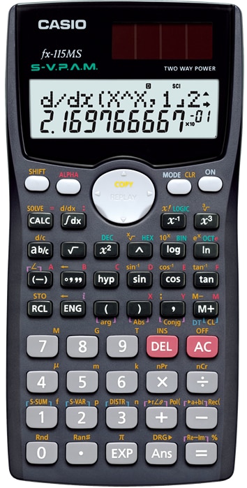
I've always been a Casio devotee. And currently my scientific calculator of choice is the FX115MS. Love it. Has every function I need. If it were programmable it would be perfection itself.

Tuesday, July 20, 2010

Where's the spec?

I've been going over the Fluke 80 Series V user's manual but I can't find the specs for the DCmV impedance when high input impedance mode is set. Input resistance is normally 10MOhm but when the "Hz %" button is held down when the meter is turned on its goes into high impedance mode in the DCmV range.

The Fluke 87 (original series) manual actually states how much it is: "The input impedance of the function (400 mV range) is changed from 10 megohms to greater than 4000 megohms." But that's for the 87 not the 87V.

Googling turned up only one source for this datum. Fortunately, it's pretty reliable since it comes from one of Fluke's own engineers. Chuck Newcombe tells us that,
If you want to measure a high impedance dc source, and the anticipated voltage is less than 600 mV, the Fluke 87V has a power-up feature that can save the day. Just hold the 'Hz %' button while you turn the meter on to remove the 10 megohm divider from the circuit. Now, the dmm's loading effect is greatly reduced, with an input resistance of 1000 Megohms or more. 
So there. For the 87V high input impedance mode value is at least 1000 Megs.

Why this isn't in the specs section of the manual boggles the mind.

Sunday, July 11, 2010

Half a Fluke


Always dreamed of having a bench multimeter. Sure can't afford a brand new Fluke. So I settled for a couple decade old 8842A. Got it off ebay. Was excited to start using it when it arrived. But just minutes into checking the various functions my heart sank when I discovered the AC functions weren't working. "Error 30" kept popping up whenever the "VAC" and "mA ~" buttons were pressed. That could only mean that the AC circuit board isn't installed! That's despite the fact the supplier had told me personally that all the functions--including AC--were working fine. But that wasn't the worst of problems. Turned out the power switch is faulty. After turning the unit off for the first I had trouble getting it switched back on. It's a pushbutton type that mechanically latches. Apparently the mechanism is already dodgy. Had to press it several times for it to stay in the down (on) position. After turning it off for a second or third time the switch just died. That was when my heart stopped. I had bought a lemon. I now had a $300 paperweight adorning my workbench.

Lesson learned. Don't buy expensive antique second hand equipment from half a world away unless you're prepared to be disappointed and unless you can afford to have it sent back in case it's not as described in the ad and/or is defective.

Fortunately that isn't the end of the story. The following day I performed CPR on the Fluke. I kept pressing the switch--gently!--while turning the unit over and on its sides. I was banking on the off and off chance that gravity might help get the switch mechanism to engage. I don't know if the turning helped at all but after a minute or so of pressing the switch actually engaged. Well, that was it--I was not ever, ever going to push that button again. No way I'm going to risk being unable to switch this meter on again.

To power the unit up and down I'm now using an extension cord that has a similar latching pushbutton switch. I've already turned the meter on and off at least a dozen times over the past few days and the unit seems to not mind. I'm just crossing my fingers it stays that way. Will eventually have to look for a service center that can replace this switch. My concern, however, is loss of calibration when they take the unit apart, and what component they might wreck!

As a precaution I've stuck a neon yellow Post-It over the 8842A's green power switch to prevent me from accidentally pressing it! Given how absent-minded I am that's bound to happen without this warning sticker.

This is a calibrated unit (well at least that's what the seller tells me) and initial tests show that it is in fact pretty accurate. I used another Fluke and did a side-by-side test of the DCV, DCmA, and ohms ranges and readings from both meter are within 0.01% of each other. The other Fluke has much less resolution so the two meters are hardly on equal footing.