Monday, February 27, 2012

Toy traffic light - the next gen is here

After so much anxiety over how to build and secure the 7-segment LEDs to top of the signal tower--and at the same time permit the cap to be removed in case the incandescent bulbs need to be replaced--I've finally come up with a workable design and modified the original signal tower toy traffic light. I've also slightly revised the draft schematic and firmware (do check out that page for a primer on the circuit). Here's a summary--in images--of the build:

PCB artwork for the main board and the LED boards. Main board is 3 x 5". The three LED boards are all 1.25 x 1.5".


Freshly etched boards. I made an extra of what I call the "platform"--the board onto which the two 7-segment LED boards named ALPHA and BETA are soldered to at right angles.


Below is the panel broken into four boards using the score and snap method. These have already been drilled (except for the extra board).


A 9-pin connector runs from the main board to the platform board. I soldered two cables back-to-back. You can see the white female plugs at the top and bottom of the photo. The other bundle of wires is the original cable for the bulbs.


That round yellow thing is a rubber pad inserted so that the signal tower and the plastic box are not rigidly connected to one another. From the looks of it the box is made of (high impact) polystyrene and is brittle. Sharp knocks and blows will crack it. The rubber acts to partly absorb shocks and prevent breakage. The three screws are tightened only to the point that the rubber is compressed a little bit.


The biggest headache for me was finding a way to mount the LED display on top of the signal tower. Fortunately I found this plastic pill and trinket storage set. The individual canisters screw on top of one another with a final screw-on cap on top. Its diameter is 50mm--exactly the same as the signal tower's. I took the cap and one of the canisters and drilled the appropriate holes. I don't have a coping saw or router so I just used the drill bit to cut out the shapes for the connectors. Messy and crude but it worked.


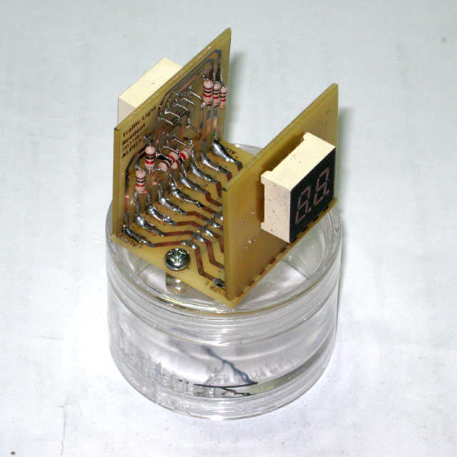


The countdown timer installed on top of the tower. I discarded the original (beige) cap of the signal tower and screwed in the canister instead.


The main board before and after the various wires were connected. You will notice the chopstick extension piece glued to the yellow push button. As in the previous model that stick pokes through a hole on top half of the plastic box. The board is secured to the base of the box using hot melt glue.


Here's a vid showing how the traffic light works.


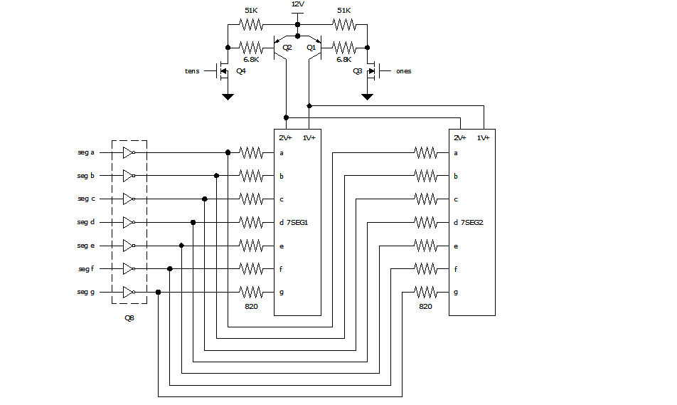
As I mentioned above I've made some revisions to the drafts of the schematic and firmware. Here are the final versions.


MCU = Microchip PIC16F1827 microcontroller
D1 = 1N5822 Schottky diode
VR = 78L05 +5V voltage regulator
7SEG1, 7SEG2 = 306IDB common anode 2-digit 7-segment LED
Q1, Q2, Q3 = TIP102 NPN Darlington transistors
Q4, Q5 = S9012 PNP transistors
Q6, Q7 = 2N7000 MOSFET transistors
Q8 = ULN2003 transistor array
LR, LR, LG = incandescent lamps


/*

Kids' Traffic Light with Countdown Timer Using an Industrial Signal Tower

Created:        January 2012
Processor:      PIC 16F1827
Compiler        mikroC Pro 5.0.0
Remarks:        see "kids traffic light.dwg" for schematic
Configuration:  power up timer, brownout reset (set to 2.5V), WDT, stack over/underflow reset -- all enabled, all others disabled

* Uses a 12VDC wall wart as power supply

* Tower light 12VDC red, amber, green incandescent lamps are switched by NPN Darlington transistors

* pushbutton:
     * when momentarily pressed: cycles through different possible modes:
          1. flashing amber
          2. flashing red
          3. alternating amber and red
          4. normal traffic light: green -> amber -> red

     * when pressed and kept depressed for over a couple of seconds LED display shows 1,2,3,4,5,6 in sequence corresponding to following go/stop on-time:
          1. 5sec
          2. 10sec
          3. 15sec
          4. 20sec
          5. 25sec
          6. 30sec
     * although LED readout can be made to show number of real-time seconds when selecting go/stop time
       showing it in the manner above provides an opportunity to teach the children how to multiply--in this case multiply by 5

* go/stop on-time is stored in EEPROM

* has 7-segment LED display
     * shows the go/stop on-time when selecting it
     * shows the remaining time before light changes
     * shows various non-numeric characters in other modes


*/


// ************************************************************************************************
//       input / output
// ************************************************************************************************

#define  lred                LATB.f3             // NPN darlington switches 12VDC incandescent lamp
#define  lamber              LATB.f2             // NPN darlington switches 12VDC incandescent lamp
#define  lgreen              LATB.f1             // NPN darlington switches 12VDC incandescent lamp

#define  pb                  PORTB.f6            // momentary contact push button
#define  tris_pb             TRISB.f6            // for setting pb pin as input
#define  wpu_pb              WPUB.f6             // for enabling weak pullup

#define  anode_ones          LATB.f5             // S9012 PNP transistor
#define  anode_tens          LATB.f4             // S9012 PNP transistor

#define  seg_a               LATA.f4             // segment a of seven segment LED common anode
#define  seg_b               LATA.f3             // segment b of seven segment LED common anode
#define  seg_c               LATA.f0             // segment c of seven segment LED common anode
#define  seg_d               LATA.f6             // segment d of seven segment LED common anode
#define  seg_e               LATA.f7             // segment e of seven segment LED common anode
#define  seg_f               LATA.f1             // segment f of seven segment LED common anode
#define  seg_g               LATA.f2             // segment g of seven segment LED common anode

// ************************************************************************************************
//       traffic light time duration
// ************************************************************************************************

#define  count_ini           250       // number of timer2 ticks to make one second

#define  ambertime           500       // in normal mode -- amount of time for amber light to be on after green and before red -- time in terms of timer2 ticks
#define  flashambertime      200       // in flashing amber mode -- amount of time for amber light to be on and amount of time to be off -- time in terms of timer2 ticks
#define  flashredtime        200       // in flashing red mode -- amount of time for red light to be on and amount of time to be off -- time in terms of timer2 ticks
#define  flashredambtime     200       // in red/amber alternate flashing mode -- amount of time for red light to be on and amount of time amber light to be on -- time in terms of timer2 ticks
#define  ledflashtime        25        // in normal mode during yield (amber light) -- amount of time the character displayed on 7-seg is flashed on and off

#define  changergtime        375       // minimum amount of time for button to be kept pressed before cycling through the green light on time -- time in terms of timer2 ticks
                                       // given 4ms timer2 tick, changergtime of 250 = 1sec real time

#define  prechangergtime     changergtime - 250  // amount of time after button is held down when all lights are turned off in preparation for possible change of green/red light on time

#define  rgtime_increm       1250      // amount of time for green/red light to be on, and multiples thereof upon continual button press -- value in terms of timer2 ticks.
#define  maxrgtime           6         // maximum allowed multiple of rgtime_increm

int16 REDGREENTIME;                    // amount of time for green/red light to be on -- time in terms of timer2 ticks
int8  RGTIME;                          // multiples of rgtime_increm such that RGTIME*rgtime_increm = REDGREENTIME


// ************************************************************************************************
//       for pushbutton
// ************************************************************************************************

#define  rising              1         // rising edge detected. used by PBedge
#define  released            1         // rising edge detected. used by PBedge
#define  falling             2         // falling edge detected. used by PBedge
#define  pressed             2         // falling edge detected. used by PBedge
#define  none                0         // no edge. used by PBedge

int8 PBval;                            // last eight values of the switch upon reading it
int8 PBedge;                           // edge detected?, 0 = no edge detect, 1 = rising edge, 2 = falling edge; other values = Not Used / Undefined for now
bit PBlevel;                           // voltage level of switch when not bouncing (hi = 1, lo = 0)

// ************************************************************************************************
//       general defines and variables
// ************************************************************************************************

#define  int1                bit
#define  int8                unsigned char
#define  int16               unsigned int
#define  int32               unsigned long

#define  on                  1
#define  off                 0

#define  input               1         // for TRISx
#define  output              0         // for TRISx

#define  analog              1         // for ANSELx
#define  digital             0         // for ANSELx

#define  addr_rgtime         0x10      // eeprom address for user selected green/red light on time

#define  disp_dash           111       // code to display a dash, for use with UpdateDisp()

#define  disp_3horiz         120       // code to display three horizontal segments, for use with UpdateDisp()
#define  disp_tophoriz       121       // code to display top horizontal segment, for use with SegmentAssign()
#define  disp_midhoriz       122       // code to display middle horizontal segment, for use with SegmentAssign()
#define  disp_botthoriz      123       // code to display bottom horizontal segment, for use with SegmentAssign()

#define  disp_brackets       130       // code to display brackets, for use with UpdateDisp()
#define  disp_left_bracket   131       // code to display left bracket, for use with SegmentAssign()
#define  disp_right_bracket  132       // code to display right bracket, for use with SegmentAssign()

#define  disp_topsquare      141       // code to display top square, for use with UpdateDisp()
#define  disp_bottsquare     142       // code to display bottom square, for use with UpdateDisp()

#define  disp_blank          255       // code to display nothing, for use with UpdateDisp()

int16 TIME = 0;                        // records how long a light has been on  -- in terms of timer2 ticks
int8  VALUE = disp_blank;              // number or character to be displayed on 7-seg LED
int8  RGSECONDS;                       // user-selected red/green on-time in real-time seconds


// ************************************************************************************************
//       for state machines
// ************************************************************************************************

// !! A C H T U N G !! 
// make sure all non user selectable modes such as _standby and _selectrgtime come AFTER user selectable
// and that _normal" is the last item in the valid user selectable modes because it is used as the max value in ProcessKey()
enum {_flashingamber, _flashingred, _flashingredamber, _normal, 
      /* the modes that follow are non-user selectable --> */ _standby, _selectrgtime} STATEMODE = _flashingamber;

enum {_stop, _yield_ini, _yield, _go} STATENORMAL = _stop;
enum {_init, _flash} STATEFLASHGREEN = _init;


// ===========================================================================================
//       LED 7-Segment Display
// ===========================================================================================

void SegmentAssign(int8 num)
{
  seg_a = 0;
  seg_b = 0;
  seg_c = 0;
  seg_d = 0;
  seg_e = 0;
  seg_f = 0;
  seg_g = 0;

  switch (num)
  {
    case 1:
      seg_b = 1;
      seg_c = 1;
      break;

    case 2:
      seg_a = 1;
      seg_b = 1;
      seg_d = 1;
      seg_e = 1;
      seg_g = 1;
      break;

    case 3:
      seg_a = 1;
      seg_b = 1;
      seg_c = 1;
      seg_d = 1;
      seg_g = 1;
      break;

    case 4:
      seg_b = 1;
      seg_c = 1;
      seg_f = 1;
      seg_g = 1;
      break;

    case 5:
      seg_a = 1;
      seg_c = 1;
      seg_d = 1;
      seg_f = 1;
      seg_g = 1;
      break;

    case 6:
      seg_a = 1;
      seg_c = 1;
      seg_d = 1;
      seg_e = 1;
      seg_f = 1;
      seg_g = 1;
      break;

    case 7:
      seg_a = 1;
      seg_b = 1;
      seg_c = 1;
      break;

    case 8:
      seg_a = 1;
      seg_b = 1;
      seg_c = 1;
      seg_d = 1;
      seg_e = 1;
      seg_f = 1;
      seg_g = 1;
      break;

    case 9:
      seg_a = 1;
      seg_b = 1;
      seg_c = 1;
      seg_d = 1;
      seg_f = 1;
      seg_g = 1;
      break;

    case 0:
      seg_a = 1;
      seg_b = 1;
      seg_c = 1;
      seg_d = 1;
      seg_e = 1;
      seg_f = 1;
      break;

    case disp_dash:          // displays a dash - middle horizontal segment
      seg_g = 1;
      break;

    case disp_3horiz:        // displays three horizontal segments
      seg_a = 1;
      seg_d = 1;
      seg_g = 1;
      break;

    case disp_tophoriz:      // displays top horizontal segment
      seg_a = 1;
      break;

    case disp_botthoriz:     // displays bottom horizontal segment
      seg_d = 1;
      break;

    case disp_left_bracket:  // displays opening bracket
      seg_a = 1;
      seg_d = 1;
      seg_e = 1;
      seg_f = 1;
      break;

    case disp_right_bracket: // displays closing bracket
      seg_a = 1;
      seg_b = 1;
      seg_c = 1;
      seg_d = 1;
      break;

    case disp_topsquare:     // displays a square on upper half of LED
      seg_a = 1;
      seg_b = 1;
      seg_f = 1;
      seg_g = 1;
      break;

    case disp_bottsquare:    // displays a square on the lower half of the LED
      seg_c = 1;
      seg_d = 1;
      seg_e = 1;
      seg_g = 1;
      break;

    default:                 // if invalid value then display blank

    case disp_blank:         // segments have already been turned off at the start of this function so do nothing
      break;
  } // switch (num)
} // void SegmentAssign(int8 num)


void UpdateDisp()
{
  static bit anode;          // flag bit multiplexing display between tens and ones place
  int8 TENS, ONES;           // contains the digit or code of the non-numeric character to be displayed in the tens and ones place

  // turn off power to 7-segment LED display.
  anode_ones = off;
  anode_tens = off;

  if (STATEMODE != _standby)         // turn on LED display only when not in _standby mode
  {
    if (VALUE < 100)                 // values >= 100 are codes for non-numeric characters
    {
      TENS = VALUE/10;
      ONES = VALUE%10;
    } // if (VALUE < 100)
    else
    {
      switch (VALUE)
      {
        case disp_dash:
          TENS = disp_dash;
          ONES = disp_dash;
          break;

        case disp_3horiz:
          TENS = disp_3horiz;
          ONES = disp_3horiz;
          break;

        case disp_tophoriz:
          TENS = disp_tophoriz;
          ONES = disp_tophoriz;
          break;

        case disp_botthoriz:
          TENS = disp_botthoriz;
          ONES = disp_botthoriz;
          break;

        case disp_brackets:
          TENS = disp_left_bracket;
          ONES = disp_right_bracket;
          break;

        case disp_topsquare:
          TENS = disp_topsquare;
          ONES = disp_topsquare;
          break;

        case disp_bottsquare:
          TENS = disp_bottsquare;
          ONES = disp_bottsquare;
          break;

        default:                       // if invalid value then display blank

        case disp_blank:
          TENS = disp_blank;
          ONES = disp_blank;
          break;
      } // switch (VALUE)
    } // else if (VALUE >= 100)

    if (anode)
    {
      if (TENS != 0)                   // do not display tens place if it's zero
      {
        SegmentAssign(TENS);
        anode_tens = on;
      }
      anode = 0;
    }
    else
    {
      SegmentAssign(ONES);
      anode_ones = on;
      anode = 1;
    }
  } // if (display)
} // void UpdateDisp()


// ===========================================================================================
//       functions
// ===========================================================================================

void ComputeRedGreenTime()
{
  REDGREENTIME = RGTIME*rgtime_increm;
  RGSECONDS = RGTIME*5;
}

void AllLightsOff()
{
  lred = off;
  lamber = off;
  lgreen = off;
}

void IniReg()
{
  // set internal clock frequency to 2MHz
  OSCCON = 0b1100000;

  TRISA = output;
  TRISB = output;
  ANSELA = digital;
  ANSELB = digital;

  tris_pb = input;

  // enable weak pull up for pushbutton
  OPTION_REG.NOT_WPUEN = 0;
  wpu_pb = 1;
  
  AllLightsOff();            // necessary to make sure incandescent lamps which should be off upon start up are off

  // Timer2 is used for state machine and switch debouncing timing tick
  // with clock = 2MHz, PR2 = 125, prescale = 1:16, postscale = 1:1
  // TMR2 will count from zero to PR2 and timer2 interrupt occurs every 125*16 / (2MHz / 4) = 4ms = timer2 tick
  T2CON = 0b110;             // postscaler = 1:1, prescaler = 1:16, timer2 on
  TMR2 = 0;
  PR2 = 125;

  WDTCON = 0b1000;           // prescale = 1:512 (16ms typical)
                             // WDTE in configuration word is configured so that WDT enabled when MCU awake and disabled when MCU asleep

  // retrieve stored green/red light on time value.
  // If eeprom-stored value is out of valid range then set it to minimum and store this value in eeprom
  // stored values are in terms of multiples of rgtime_increm such that stored value multiplied by rgtime_increm = time in terms of TMR2 ticks
  RGTIME = EEPROM_Read(addr_rgtime);
  if (RGTIME == 0 || RGTIME > maxrgtime)
  {
    RGTIME = 1;
    EEPROM_Write(addr_rgtime, RGTIME);
  }
  ComputeRedGreenTime();                     // REDGREENTIME = RGTIME*rgtime_increm;

  // initialize push button
  PBval = 0xFF;
  PBlevel = hi;
} // void InitRegisters()


// amber flashes on and off at a rate determined by flashambertime
// LED display shows the character stored in VALUE
void FlashingAmber()
{
  static bit flag;

  if (++TIME < flashambertime)
  {
    if (flag)
    {
      lamber = on;
      VALUE = disp_brackets;
    }
    else
    {
      lamber = off;
      VALUE = disp_blank;
    }
  }
  else
  {
    if (flag)
      flag = 0;
    else
      flag = 1;
    TIME = 0;
  }
} // void FlashingAmber()


// red flashes on and off at a rate determined by flashredtime
// LED display shows the character stored in VALUE
void FlashingRed()
{
  static bit flag;

  if (++TIME < flashredtime)
  {
    if (flag)
    {
      lred = on;
      VALUE = disp_brackets;
    }
    else
    {
      lred = off;
      VALUE = disp_blank;
    }
  }
  else
  {
    if (flag)
      flag = 0;
    else
      flag = 1;
    TIME = 0;
  }
} // void FlashingRed()


// red and amber turn on alternately at a rate determined by flashredambertime
// LED display shows the character stored in VALUE
void FlashingRedAmber()
{
  static bit flag;

  if (++TIME < flashredambtime)
  {
    if (flag)
    {
      lamber = off;
      lred = on;
      VALUE = disp_topsquare;
    }
    else
    {
      lred = off;
      lamber = on;
      VALUE = disp_bottsquare;
    }
  }
  else
  {
    if (flag)
      flag = 0;
    else
      flag = 1;
    TIME = 0;
  }
} // void FlashingRedAmber()


// normal traffic light operation: green --> amber --> red
// red/green light on-time is user selectable
// LED display shows the countdown time in seconds during red and green light 
// LED display shows a flashing "--" during amber light, blink rate determined by ledbflashtime
void Normal()
{
  static int8 COUNTER;
  static bit toggle;

  switch (STATENORMAL)
  {
    case _stop:
      if (++TIME < REDGREENTIME)
      {
        lred = on;
        if (--COUNTER == 0)
        {
          --VALUE;
          COUNTER = count_ini;
        }
      }
      else
      {
        STATENORMAL = _go;
        TIME = 0;
        COUNTER = count_ini;
        VALUE = RGSECONDS;
        lred = off;
      }
      break;

    case _yield_ini:
      toggle = 1;
      VALUE = disp_dash;
      COUNTER = ledflashtime;
      TIME = 0;
      STATENORMAL = _yield;
      break;

    case _yield:
      if (++TIME < ambertime)
      {
        lamber = on;

        if (--COUNTER == 0)
        {
          if (toggle)
          {
            VALUE = disp_blank;
            toggle = 0;
          }
          else
          {
            VALUE = disp_dash;
            toggle = 1;
          }
          COUNTER = ledflashtime;
        }
      }
      else
      {
        STATENORMAL = _stop;
        TIME = 0;
        COUNTER = count_ini;
        VALUE = RGSECONDS;
        lamber = off;
      }
      break;

    case _go:
      if (++TIME < REDGREENTIME)
      {
        lgreen = on;
        if (--COUNTER == 0)
        {
          --VALUE;
          COUNTER = count_ini;
        }
      }
      else
      {
        STATENORMAL = _yield_ini;
        lgreen = off;
      }
      break;

    default:
      TIME = 0;
      STATENORMAL = _yield;
  } // switch (STATENORMAL)
} // void StateMachNormal()


void StateMachMain()
{
  switch (STATEMODE)
  {
    case _normal:
      Normal();
      break;

    case _flashingamber:
      FlashingAmber();
      break;

    case _flashingred:
      FlashingRed();
      break;
      
    case _flashingredamber:
      FlashingRedAmber();
      break;

    case _standby:           // do nothing mode where all bulbs are off. used when changing red/green on-time
      break;
      
    case _selectrgtime:      // er uhhh, I guess we do nothing as well
      break;

    default:
      STATEMODE = _normal;
  }
} // void StateMachMain()


void DebounceSwitch()
{
  // shift all bits to the left
  // if switch reading is hi then let pb_val bit 0 = 1
  PBval <<= 1;
  if (pb)
    ++PBval;

  PBedge = none;

  // if level is lo and all bits of pb_val are now hi then
  // a rising edge has been detected
  // switch is considered just released when rising edge is detected
  // switch level is now hi
 if ((!PBlevel) && (PBval == 0xFF))
  {
    PBlevel = hi;
    PBedge = rising;
  }

  // if level is hi and all bits of pb_val are now low then
  // a falling edge has been detected
  // switch is considered just pressed when falling edge is detected
  // switch level is now lo
  if ((PBlevel) && (!PBval))
  {
    PBlevel = lo;
    PBedge = falling;
  }
} // void DebounceSwitch()


void ProcessKey()
{
  int8 MODE;                           // temporary storage of current STATEMODE

  static  int16  PBPRESSTIMETOTAL = 0; // Keeps track of how long PB is depressed in terms of timer2 ticks
                                       // Keeps track of total time from falling edge (switched pressed) to rising edge (switch released).
                                       // if less than changergtime then we know the keypress is momentary and user wants to change modes

  static  int16  PBPRESSTIME = 0;      // Keeps track of how long PB is depressed in terms of timer2 ticks
                                       // this variable is reset every time it exceeds changergtime
                                       // every time it exceeds changergtime red/green on-time is incremented until masrgtime and then it cycles back to one

  DebounceSwitch();
  MODE = STATEMODE;

  if (PBlevel == lo)
  {
    if (++PBPRESSTIMETOTAL == prechangergtime)
    {
      AllLightsOff();
      STATEMODE = _standby;
    }

    if (++PBPRESSTIME >= changergtime)
    {
      PBPRESSTIME = 0;
      if (++RGTIME > maxrgtime)
        RGTIME = 1;
//      EEPROM_Write(addr_rgtime, RGTIME);
//      ComputeRedGreenTime();                     // REDGREENTIME = RGTIME*rgtime_increm;
      STATEMODE = _selectrgtime;
      VALUE = RGTIME;                            // RGTIME will be displayed on the LED readout
    } // if (++PBPRESSTIME >= changergtime)
  } // if (PBlevel == lo)

  if (PBedge == released)
  {
    if (PBPRESSTIMETOTAL < changergtime)         // if pushbutton was only momentarily pressed then change to the next mode
    {
      STATEMODE = ++MODE;
      if (STATEMODE == _normal)
        STATENORMAL = _yield_ini;                // this is necessary to start normal traffic light mode properly
      else if (STATEMODE > _normal)
        STATEMODE = 0;
    } // if (PBPRESSTIMETOTAL < changergtime)
    else  // green/red light on time has been changed so go to normal traffic light mode and begin with amber light
    {
      EEPROM_Write(addr_rgtime, RGTIME);
      ComputeRedGreenTime();                     // REDGREENTIME = RGTIME*rgtime_increm;
      STATEMODE = _normal;
      STATENORMAL = _yield_ini;
    }

    AllLightsOff();          // turn off all bulbs and let state machine take care of which ones to turn on
    TIME = 0;                // reset timer so that whatever mode has been selected, light will go through full time allotted
    PBPRESSTIMETOTAL = 0;
    PBPRESSTIME = 0;
  } // if (PBedge == released)
} // void ProcessKey()


void main()
{
  IniReg();

  while(1)
  {
    if (PIR1.TMR2IF)
    {
      PIR1.TMR2IF = 0;
      asm{clrwdt}
      UpdateDisp();
      ProcessKey();
      StateMachMain();
    } // if (PIR1.TMR2IF)
  } // while(1)
} // void main()

Monday, February 20, 2012

AC load switching via infrared remote control

Laziness is the mother of invention. Not wanting to get out of bed to turn off the room lights, it occurred to me to build a circuit--one that I may end up using or not--which would switch the lights off/on when it receives the proper signals from a TV remote control. Here's the original design:


After breadboarding and testing the above it hit me: Why not add more features such as setting the amount of time the light (or whatever load it may be) will remain on, or time elapsed before it automatically turns on. Adding these capabilities would merely require changes to the software. But because I would need the LEDs as indicator lights for various functions--eg. making them blink as user feedback--they have to be controlled separately from the triac/load. Since the 8-pin MCU has unused pins it was trivial assigning each LED a MCU pin of its own. Here's the final circuit. I've changed the triac gate current limiting resistor value as well:


MCU = Microchip PIC12F615 microcontroller
IRR = Osram SFH5110-38 IR receiver 38kHz
Z1 = 1N4734A 5.6V 1W zener diode
Q1 = 2N7000 n-channel enhancement MOSFET transistor
TRIAC = Teccor Q401E3 400V 1A triac

Z1, C1, C2, and D1 comprise a half-wave transformerless power supply providing approximately 5VDC. With C1 = 1uF the circuit is designed to run off 220VAC 60Hz mains, providing a theoretical maximum current of around 80mA RMS. The above may or may not work with 110VAC since at that voltage the available DC current is halved. For 110VAC 60Hz use, doubling the capacitance to 2uF will halve the capacitive reactance and thus let through twice the current. Capacitive reactance is given by:

XC = (6.28fC)-1

where
f = frequency of the AC line in Hertz
C = capacitance in farads 

Therefore, with C = 2uF XC = 1327ohms. RMS current is therefore = 110VAC/1327 = 83mA RMS

One leg of the mains is common to both DC and AC lines. This is necessary for the triac to be triggered by the DC circuit.

Because the circuit doesn't use a transformer any part of it is potentially lethal to the touch. The net labeled 5V is 5VDC with respect to the circuit ground. But it is 220VAC with respect to the other leg of the AC line and it can be as much as 110VAC with respect to earth ground, so beware! It goes without saying that errors in connecting/ soldering of the components of the power supply could result in unintended and undesirable fireworks and tripping of the building's breakers/fuses. Be damn careful when designing and building circuits involving mains voltage. I come down with OCD and anxiety disorder every time. You can't check and recheck enough times that you've done everything right.

R1 is an ordinary carbon resistor and functions as a fuse. It's supposed to blow if current through the circuit (but not the load and MT1 to MT2 of the triac) exceeds around 100mA. Given an 18-ohm 250mW resistor, current at which its dissipation is 250mW is = √(0.25/18) = 118mA. So the resistor should theoretically fry if it exceeds this value for over a fraction of a second.

Note, however, that given 220V RMS, its peak voltage = 220√2 = 311V. With C1 = 1uF XC = 2653ohms. Therefore, peak current = 311/2653ohms = 117mA. Thus the resistor experiences instantaneous dissipation of 250mW 120 times a second (two peaks per cycle for a 60Hz line). If this fuse keeps blowing for no apparent reason, lower it to 15ohms. Of course this is a poor man's version of a fuse resistor and is suboptimal and may even fail to protect the components downstream. Better than none though.

R2 and C3 were added as per suggestion of the Osram datasheet. When I was bench testing the breadboarded version which I powered using the PICkit2, I found that adding R2 and C3 did boost the performance. Apparently the PICkit2 wasn't supplying clean or sufficient power. Having used the above transformerless power supply design for about a decade in a good number of circuits I know there are regulated voltage and ripple voltage issues with it (because it's just a half-wave supply). And so adding R2 and C3 is mandatory.

Triac gate trigger is such that current flows from MT1 to gate (rather than from gate to MT1), hence the triac operates in Quadrants 2 and 3--which require much less gate trigger current. For a discussion of triac quadrants and triggering read the section "Load Switching."

Given the zener voltage of 5.6V and D1 forward voltage VF of 0.7V @20mA (see graphs for 1N400x), our VDD = 5.6 - 0.7 = 4.9VDC. According to the Teccor datasheet maximum required gate current for quadrants 2 and 3 operation is 10mA while maximum gate voltage VGT is 1.3V. Deducting VGT from VDD we're left with 4.9 - 1.3 = 3.6V. There's also a voltage drop across Q1. According to the graphs in the 2N7000 specs sheet the drain-to-source resistance RDS at a gate-to-source voltage of 5.0V and gate current of 10mA is almost 1.5ohms. Using Ohm's Law the drain-to-source voltage VDS = 1.5ohms x 10mA = 15mV. This is negligible, and even if quadrupled VDS would still be just around 60mV. So we can disregard the Q1 voltage drop and take 3.6V as the voltage across triac gate resistor RT. To obtain 10mA of gate current we apply good ol' Ohm's Law again: 3.6V / 10mA = 360ohms. Closest standard 5% resistor value is either 390 or 330ohms. We pick the lower value to make sure there's enough current to meet the maximum requirement of 10mA. With 330ohms the triac gate current = 3.6 / 330 = 10.9mA. Resistor power dissipation  = I2R = 0.01092(330) =39mW. Ostensibly this means we can use a 1/8-watt resistor. But the 10mA current we obtained is just a theoretical value. Its true value depends largely on the triac's VGT which will probably be much less than the maximum quoted 1.3V. Now supposing that VGT = 0 and our 5% tolerance 330-ohm resistor has in fact a value = 330*95% = 313 ohms. Gate current would then be 4.9V / 313ohms = 16mA. Resistor power dissipation would thus be = 0.0162313 = 80mW. This is still some 35% less than 1/8W. Therefore, we can in fact use a 1/8-watt resistor.

Currently the only buttons on the TV remote control which will make the circuit do anything are the keys for digits 1 and 0. Pressing "1" turns load on, while "0" switches it off. Upon power up the load is forced to turn on. In the case of the room light, this means that flipping the wall switch on will turn the light on--as we would want it to. The light can then be turned off via this switch or through the use of the remote control.

The firmware I have thus far is tailored for the Philips RC-5 infrared communications protocol (visit that link for an explanation for the rationale/basis of the signal decoding firmware below). I'm planning to make the circuit respond to both the RC-5 and Sony SIRC protocol, letting the firmware determine which of the protocols it's receiving (and rejecting other protocols) and deciding of course whether the received codes correspond to any of those which it should respond to and take action. As I said above, I want to extend the range of capabilities of this circuit and add stuff like timer features. So it's back to the drawing board deciding which buttons will serve as timer functions and writing the appropriate software. And as has probably already popped into your head, we wouldn't want our lights or whatever load to turn on/off when we intended to change channels on the TV! Such techniques as using two-button codes (e.g. the "Menu" and "1" buttons need to be pressed in rapid succession--i.e., within a prescribed time frame--to turn the load on) or keeping the button pressed for one second or so (e.g., command is received by the circuit, say, 5 to 10 times before action is taken) may be employed.  

/*

AC LOAD SWITCHING USING A TV REMOTE CONTROL
February 2012

processor = PIC12F615
compiler = mikroC v5.0.0
configuration word = power up timer, brownout reset, and WDT enabled; all else disabled. Internal Oscillator = 4MHz

*/


#define  load                GPIO.f2             // 2N7000 sinks triac gate current
#define  ledg                GPIO.f4             // green led  -- multifunction status led, not just on indicator
#define  ledr                GPIO.f1             // red led    -- multifunction status led, not just off indicator

#define  irr                 GPIO.f5             // Osram SFH5110-38 infrared receiver
#define  tris_irr            TRISIO.f5           // for use with setting the appropriate pin as input
#define  ioc_irr             IOC.f5              // for use with enable interrupt on change for irr

// RC5 decoding defines

#define  _full               1
#define  _half               0

// one full bit period for RC5 = 1.778ms; one half bit period = 0.889ms
// given clock = 4MHz and TMR0 initial value = 0 and timer0 prescale = 1:16, TMR0 overflows every 256 x 16 / 1MHz = 4.096ms
// 4.096ms / TMR0 count = 4.096 / 256 = 0.016ms per TMR0 count
// 1.778 / 0.016ms = 111   this is the TMR0 count when time elapsed is 1.778ms
#define  _fullbit            111                                     // full bit period of RC5
#define  _tolerance          25                                      // tolerance in percent, to be added/subtracted to/from half and full bit periods to create range of acceptable pulse widths
                                                                     // !! THIS HAS TO BE INTEGER NOT FLOATING POINT !!
                                                                     // !! MAXIMUM VALUE = 33%, ELSE halfbit_uplim WILL BE GREATER THAN fullbit_uplim

#define  _halfbit            _fullbit / 2                            // half bit period of RC5

#define  halfbit_lolim       _halfbit - (_halfbit * _tolerance / 100) // minimum pulse duration for half bit period
#define  halfbit_uplim       _halfbit + (_halfbit * _tolerance / 100) // maximum pulse duration for half bit period
#define  fullbit_lolim       _fullbit - (_fullbit * _tolerance / 100) // minimum pulse duration for full bit period
#define  fullbit_uplim       _fullbit + (_fullbit * _tolerance / 100) // maximum pulse duration for full bit period


#define  int1                bit
#define  int8                unsigned char
#define  int16               unsigned int
#define  int32               unsigned long

#define  on                  1
#define  off                 0

#define  input               1         // for TRISx
#define  output              0         // for TRISx

#define  analog              1         // for ANSELx
#define  digital             0         // for ANSELx


// ===========================================================================================
//       Global Variables
// ===========================================================================================

int8     PULSEWIDTH;         // contains the measured pulse width (to get the real value in millisec multiply by 16)
int8     RC5BITS;            // contains the bit number (excluding the start bit) of the RC5 word currently being received
int8     RC5FCSYS;           // contains the RC5 Field bit, Control Bit, and the 5-bit System Address
int8     RC5COMM;            // contains the RC5 6-bit Command code
int8     RC5COMMPREV;        // contains the previous RC5 6-bit Command code
int8     TEMP;               // temporary memory

bit      rc5_on;             // 1 = irr output has been high for >4millisec and then goes low; this indicates a RC5 start bit
                             // 0 = irr output has been low for >4millisec and then goes high. This is an abnormal state and is an error
                             // rc5_on is also reset to 0 when all bits of word have been received
bit      halfper_prev;       // 1 = the last IOC was a half bit period, 0 = the last IOC occured after a full bit period
bit      key_pressed;        // 1 = button has been pressed and valid RC5 word stored

bit      rc5_read_error;     // 1 = read error, pulse width of either a zero or one bit is outside the acceptable limits; the data packet should be discarded
bit      bit_period;         // _full = 1 = one full bit period, _half = 0 = half bit period
bit      curr_bit;           // contains the latest decoded value of the bit of the RC5 word being received
bit      con_bit_prev;        // contains the control bit of the previous decoded RC5 word

// used to monitor if a key has been pressed and if yes is the key being held down or is a new press
// _key_none = no key pressed
// _key_new = new key pressed. It may be the same button but it was released and pressed again, ie., the Control bit has toggled
// _key_same = IR signal from the same key. Button is depressed and has not been released.
enum {_key_none, _key_new, _key_same} KEY = _key_none;


// ===========================================================================================
//       Functions
// ===========================================================================================

void IniReg()
{
  ANSEL = digital;
  TRISIO = output;
  GPIO = 0;
  
  tris_irr = input;

  OPTION_REG = 0b10000011;   // prescaler assigned to timer0
                             // prescale = 1:16
                             // timer0 uses internal clock instruction cycle
                             // weak pull ups disabled

  // enable interrupt on change
  // intialize pin connnected to ir receiver to interrupt on input change
  INTCON.GPIE = on;
  ioc_irr = on;

  INTCON.GIE = 1;
  INTCON.PEIE = 1;

  key_pressed = 0;
  load = on;
  ledg = on;
  ledr = off;
} // void IniReg()


// this function determines whether the key pressed is a:
// 1. _key_none = no key press has been detected
// 2. _key_new = a different key has been pressed or the same key has been released and pressed again
// 3. _key_same = the same key is still held down
// If no key is press is detected for > _idle_time then firmware goes into standby mode and display is turned off
void ProcessKey()
{
  if (key_pressed)
  {
    key_pressed = 0;
    if ((RC5COMM == RC5COMMPREV) && (RC5FCSYS.f5 == con_bit_prev))
      KEY = _key_same;
    else           // if current key is not the same as previous key or if current control bit not the same as previous
      KEY = _key_new;

    RC5COMMPREV = RC5COMM;
    con_bit_prev = RC5FCSYS.f5;
  } // if (key_pressed)
  else
    KEY = _key_none;
} // void ProcessKey()


void LoadControl()
{
  switch (KEY)
  {
    case _key_new:
      switch (RC5COMM)
      {
        case 0:
          load = 0;
          ledg = off;
          ledr = on;
          break;
        
        case 1:
          load = 1;
          ledg = on;
          ledr = off;
          break;

        default:
          break;
      } // switch (RC5COMM)
      break;
    
    case _key_same:
      break;

    case _key_none:
      break;

  } // switch (KEY)
} // void LoadControl()


void interrupt()
{
  // interrupt on change
  if (INTCON.GPIF)
  {
    PULSEWIDTH = TMR0;
    TMR0 = 0;
    TEMP = GPIO;            // a read of GPIO is necessary before GPIF can be cleared
    INTCON.GPIF = 0;

    if (rc5_on && !rc5_read_error)
    {
      if (PULSEWIDTH >= halfbit_lolim && PULSEWIDTH <= halfbit_uplim)
        bit_period = _half;
      else if (PULSEWIDTH >= fullbit_lolim && PULSEWIDTH <= fullbit_uplim)
        bit_period = _full;
      else
        rc5_read_error = 1;

      if (bit_period == _half && halfper_prev == 0)
      {
        halfper_prev = 1;    // last IOC occured after a full bit period, so this current half bit period needs to be paird with the half bit period
      }
      else // if (bit_period == _full || halfper_prev == 1)
      {
        halfper_prev = 0;
        if (irr)             // rising edge, indicates logic zero
          curr_bit = 0;
        else                 // falling edge, indicates logic one
          curr_bit = 1;

        if (RC5BITS <= 6)
        {
          RC5FCSYS <<= 1;
          RC5FCSYS.f0 = curr_bit;
        }
        else
        {
          RC5COMM <<= 1;
          RC5COMM.f0 = curr_bit;
        }
        if (++RC5BITS >=13)
        {
          rc5_on = 0;
          key_pressed = 1;
        }
      } // else
    } // if (rc5_on && !rc5_read_error)

    // if timer0 interrupt flag is set then ir_rx output was low/high for >4ms before the IOC that just occurred
    if (INTCON.T0IF)
    {
      INTCON.T0IF = 0;
      RC5BITS = 0;
      RC5FCSYS = 0;
      RC5COMM = 0;
      rc5_read_error = 0;
      rc5_on = 0;
      if (!irr)                        // falling edge; pulse was high for >4ms so this is considered the start bit of RC5 word
        rc5_on = 1;
    } // if (INTCON.T0IF)
  } // if (INTCON.GPIF)
} // void interrupt()


void main()
{
  IniReg();

  while(1)
  {
    asm{clrwdt}
    ProcessKey();
    LoadControl();
  }
}


Decided to print a dual board artwork--just copied and pasted the original pcb layout. Each board is 2x2". Since the effort and time that goes into developing and etching one presensitized panel is practically the same whether it's 1x1" or 4x6" might as well make a dual board. Going for four is too much, specially since this is a prototype. I scored and snapped the panel into two boards after drilling all the holes.


The following pcb board has been tested to work. I used a 23-watt compact fluorescent lamp as the load. Unfortunately, it doesn't perform as flawlessly as the breadboarded version. Commands sent to the board are not always picked up properly and so the load doesn't get switched immediately upon key press. I suspect a power supply issue. I'm going to use a 220VAC-to-220VAC isolation transformer to power the board and probe the circuit with a DMM.


You will notice that the LEDs are pointing up while the adjacent infrared receiver is facing 90 degrees away. I'll bend either the sensor or the LEDs to make them face the same way after I've decided which way this board is going to be mounted and where the IR receiver needs to point.

Sunday, February 19, 2012

Saturday, February 4, 2012

Just having a little fun

This circuit was meant to test an idea but the idea turned out to be a dead end. So I ended up just playing with the circuit. Red, green and blue LEDs are turned on in sequence. Because of the difference in light intensity I've used different resistors values for each of the colors to try and even the output. Position of the potentiometer is read by the PIC16F1824's ADC. The two least significant bits of the 10-bit ADC output are ignored and the 8-bit value is copied to TMR0 and timer0 sets the amount of time each LED is on.

The white cylinder over the LEDs is just an old milky-white colored 35mm film canister. But it makes a heck of difference on how the light output is seen by the human eye. Certainly far more interesting with it. By varying the direction in which the LEDs point different light patterns on the cylinder can be created.

The MCU is run at 1MHz. LED switching occurs in the interrupt service routine. Maximum switching frequency is approximately 325Hz--each LED is on for just around 1ms. Minimum frequency is around 1.27Hz. Period T = on-time of each LED x number of LEDs. Frequency = 1/T. Timer0 is used for timing the LEDs. Its prescale is set to 256. With the clock running at 1MHz, time for one instruction cycle = 4/1MHz = 4µs. Timer0 tick = TMR0 x 256 x 4µs. The reset value of TMR0 can range from zero to 255 depending on the position of the potentiometer.

Timer2 is used to periodically read the pot and store its value in a variable which then gets copied to TMR0 during every timer0 interrupt.


#define  int1                bit
#define  int8                unsigned char
#define  int16               unsigned int
#define  int32               unsigned long

#define  on                  1
#define  off                 0

#define  _on                 0
#define  _off                1

#define  yes                 1
#define  no                  0

#define  input               1         // for TRISx
#define  output              0         // for TRISx

#define  analog              1         // for ANSELx
#define  digital             0         // for ANSELx

#define  lred                LATC.f0             // red led
#define  lgreen              LATC.f1             // green led
#define  lblue               LATC.f2             // blue led

#define  tris_lred           TRISC.f0            // for setting LED pin as output
#define  tris_lgreen         TRISC.f1            // for setting LED pin as output
#define  tris_lblue          TRISC.f2            // for setting LED pin as output

#define  an_lred             ANSELC.f0           // for setting LED pin as digital
#define  an_lgreen           ANSELC.f1           // for setting LED pin as digital
#define  an_lblue            ANSELC.f2           // for setting LED pin as digital

#define  ch_pot              3                   // analog channel of potentiometer

// ==================================================================================================================
//          global variables
// ==================================================================================================================

int8 TMR0COUNT;

// ==================================================================================================================
//          functions
// ==================================================================================================================

void IniReg()
{
  OSCCON    = 0b1011000;     // internal clock = 1MHz

  // set LED pins as output
  tris_lred = 0;
  tris_lgreen = 0;
  tris_lblue = 0;
  
  // set LED pins as digital
  an_lred = 0;
  an_lgreen = 0;
  an_lblue = 0;

  lred = 1;                  // start off with red LED
  
  // Timer0 setup
  OPTION_REG = 0b10000111;   // Weak pull ups disabled
                             // timer0 uses internal clock,
                             // prescaler assigned to timer0, prescaler = 1:256
  TMR0 = 0;
  INTCON.TMR0IE = 1;         // timer0 interrupt enable
  
  // Timer2 setup
  // with a 1MHz clock, prescale = 1:16, postscale = 1:1, PR2 = 200
  // timer2 tick = 250 * 64 / (1MHz/4) = 64ms
  T2CON = 0b111;             // timer2 on, prescale = 1:64, postscale = 1:1
  PR2 = 250;                 // timer2 counts up from zero until the value of PR2 and then resets

  // Analog to Digital Coverter setup
  ADCON0 = ch_pot << 2;      // shift in analog channel to be made active
  ADCON0.ADON = 1;           // turn on ADC
  ADCON1 = 0;                // left justified, Fosc/2, Vss as negative reference, Vdd as positive reference

  INTCON.GIE = 1;            // global interrupt enabled
} // void IniReg()


/* =========================================================================================================

According to PIC12F1824 Silicon Errata sheet DS80510D the ADC unit in certain silicon revisions is buggy:

"An ADC conversion may not complete under these conditions:
1. When FOSC is greater than 8 MHz and it is the clock source used for the ADC converter.
2. The ADC is operating from its dedicated internal FRC oscillator and 
the device is not in Sleep mode (any FOSC frequency). 
When this occurs, the ADC Interrupt Flag (ADIF) does not get set, the GO/DONE bit does not get cleared, 
and the conversion result does not get loaded into the ADRESH and ADRESL result registers."

mikroC Pro compiler's Adc_Read() built-in ADC function uses the FRC oscillators o it cannot be used.

The workaround used here is as per method 1 in the said errata:
"Select the system clock, FOSC, as the ADC clock source 
and reduce the FOSC frequency to 8 MHz or less when performing ADC conversions."

=========================================================================================================  */

int8 ADC()
{
  ADCON0.GO = 1;                       // start ADC conversion
  while (ADCON0.GO) ;                  // just wait until AD conversion is done
  return ADRESH;                       // return only the 8 most significant bits of the 10-bit value
}


void interrupt()
{
  if (INTCON.TMR0IF)
  {
    TMR0 = TMR0COUNT;
    if (lred)
    {
      lgreen = on;
      lred = off;
    }
    else if (lgreen)
    {
      lblue = on;
      lgreen = off;
    }
    else
    {
      lred = on;
      lblue = off;
    }
    INTCON.TMR0IF = 0;
  }
}


void main()
{
  IniReg();

  while(1)
  {
    if (PIR1.TMR2IF)
    {
      TMR0COUNT = ADC();
      PIR1.TMR2IF = 0;
    }
  } // while(1)
} // void main()

Friday, January 27, 2012

Toy traffic light--the next generation

Just minutes after I presented the signal tower traffic light to the kids last week and briefed them on how it works and how to change the go/stop time duration, the eldest told me I should put a digital countdown timer on top of the tower so they'll know how many seconds there are remaining before red turns green and green turns amber. I was dumbstruck. Why the heck didn't I think of that?! His suggestion is nothing short of brilliant. These kids are geniuses (of course I'm fracking biased!).

So it was back to the drawing board for v2.0. My boss wants his traffic light by this week. Told him I can't since I need time to design the circuit and the pcb and write the software and think about how to mount the LED readouts and then finally put everything together. Working for 7-year olds is tough.

Well, writing the firmware was a breeze. The state machine structure lends itself to easy modification. And in the process bulbs went off in my head and I added other features including a new mode wherein the red and amber lights alternate, with the same on-time as the flashing red and flashing amber modes of 0.8sec. And since a seven segment LED display is going to be used anyway why not put it to use even in modes other than normal traffic light mode. So during the flashing red, flashing amber, and alternating red and amber modes the LED will be showing various non numeric characters just to add to the light show. And most importantly I've dumped the use of the green bulb as feedback for the number of seconds for go/stop on-time. The LED now displays "1", "2"... up to "6" to indicate 5sec, 10sec,... 30sec of go/stop on-time. I could easily show the actual number of seconds on the display but I didn't because I think it would be good multiplication practice for the kids. At least they get to know by heart the products of 1 x 5, 2 x 5, ... up to 6 x 5.


Parts list:
PS - AC to DC adapter 12VDC 1000mA output
D1 - 1N5822 Schottky diode
MCU - PIC16F1827 microcontroller
VR - 78L05 voltage regulator
7SEG1, 7SEG2 - seven segment LED display common anode
Q1, Q2 - S9012 PNP transistors
Q3, Q4 - 2N7000 n-channel enhancement MOSFET
Q5, Q6, Q7 - TIP102 NPN Darlington transistor
Q8 - ULN2003 transistor array

My initial design had the LED powered from the 5V rail. This required using an L7805 which has an output capacity of at least 1000mA instead of the 78L05 which can only put out 100mA. Computations showed that because of the large headroom (12V - 5V) and large current draw (around 150mA) the power dissipation of the voltage regulator would raise its temperature close to 100 Celsius and thus necessitate a heatsink. Shudder! A heatsink eats up so much space. So it occurred to me to just power the LED directly off the unregulated supply of 12V. Of course the power dissipation issue would move over to the LED current limiting resistors but that is easily taken care of by employing 1/4-W resistors instead of 1/8-W. Trivial. In the initial 5V design it was a simple matter of using PNP transistors to provide power to the common anode seven segment LEDs. But with the emitter at 12V the base of the PNP can no longer be directly hooked up to the 5-volt MCU. In order to switch the PNP I've opted to use the 2N7000 MOSFET. Using an NPN would've been just as effective but it would've required the addition of a base current limiting resistor. The less components on the board the better. In order for the MOSFET and PNP setup to work properly the base of the PNP must be pulled up to the emitter voltage when the 2N7000 is off, else the base will be left floating. Thus, the 51Kohm resistor. When the 2N7000 is turned off the pull-up resistor brings the base voltage to 12V thus switching off the PNP and cutting supply to the LED display.

I've decided to install two LED displays back-to-back both showing exactly the same readout. Each segment will be provided around 10mA. Because the current draw is double (two LED displays) and because of the 12VDC supply the MCU pins cannot be used to directly sink the current. Therefore a ULN2003 transistor array takes care of the power switching.

The tens and ones digits on the display are multiplexed and switched every 4ms giving a frequency of 1/ (4ms x 2) = 125Hz. That's more than fast enough to provide a flicker-free display.

Because of the additional function calls to update the LED display I've increased the the clock rate from the previous 500kHz to 2MHz. Timer2 tick is still 4ms. A check using the Saleae Logic shows that at 2MHz it usually takes only about half a millisecond to go through all the functions. However, when go/stop on-time is changed the time consumed jumps to over 3ms. Measurement shows the ComputeRedGreenTime() function takes 0.50ms. Multiplication does take time but I discovered the king of snails is the EEPROM write. Storing the one byte stop/go on-time takes a whopping 2.66ms. But this is actually better than the datasheet spec of 4.0ms typical and 5.0ms max. Given the half millisecond average (when the user is not selecting a stop/go time), I could actually have retained the 500kHz clock. The savings on power is, however, marginal and negligible compared to what the bulbs and LEDs consume.

I'll post a vid and pics of the new and improved traffic light when I finally build the circuit and figure out how to mount the seven segment LED boards on top of the tower and still be able to have access to the screw of the tower's cap and protect the boards from the 7-, 6-, and 4-yr old demotion team!.

/*

Kids' Traffic Light with Countdown Timer Using an Industrial Signal Tower

Created:        January 2012
Processor:      PIC 16F1827
Compiler        mikroC Pro 5.0.0
Configuration:  power up timer, brownout reset (set to 2.5V), WDT, stack over/underflow reset -- all enabled, all others disabled

* Uses a 12VDC wall wart as power supply

* Tower light 12VDC red, amber, green incandescent lamps are switched by NPN Darlington transistors

* pushbutton:
     * when momentarily pressed: cycles through different possible modes:
          1. flashing amber
          2. flashing red
          3. alternating amber and red
          4. normal traffic light: green -> amber -> red

     * when pressed and kept depressed for over a couple of seconds LED display shows 1,2,3,4,5,6 in sequence corresponding to following go/stop on-time:
          1. 5sec
          2. 10sec
          3. 15sec
          4. 20sec
          5. 25sec
          6. 30sec
     * although LED readout can be made to show number of real-time seconds when selecting go/stop time
       showing it in the manner above provides an opportunity to teach the children how to multiply--in this case multiply by 5

* go/stop on-time is stored in EEPROM

* has 7-segment LED display
     * shows the go/stop on-time when selecting it
     * shows the remaining time before light changes
     * shows various non-numeric characters in other modes


*/


// ************************************************************************************************
//       input / output
// ************************************************************************************************

#define  lred      LATB.f4                       // NPN darlington switches 12VDC incandescent lamp
#define  lamber    LATA.f6                       // NPN darlington switches 12VDC incandescent lamp
#define  lgreen    LATB.f5                       // NPN darlington switches 12VDC incandescent lamp

#define  pb        PORTA.f5                      // momentary contact push button
#define  tris_pb   TRISA.f5

#define  anode_ones          LATA.f0             // S9012 PNP transistor
#define  anode_tens          LATA.f1             // S9012 PNP transistor

#define  seg_a               LATA.f2             // segment a of seven segment LED common anode
#define  seg_b               LATA.f3             // segment b of seven segment LED common anode
#define  seg_c               LATA.f4             // segment c of seven segment LED common anode
#define  seg_d               LATB.f0             // segment d of seven segment LED common anode
#define  seg_e               LATB.f1             // segment e of seven segment LED common anode
#define  seg_f               LATB.f2             // segment f of seven segment LED common anode
#define  seg_g               LATB.f3             // segment g of seven segment LED common anode

// ************************************************************************************************
//       traffic light time duration
// ************************************************************************************************

#define  count_ini           250       // number of timer2 ticks to make one second

#define  ambertime           500       // in normal mode -- amount of time for amber light to be on after green and before red -- time in terms of timer2 ticks
#define  flashambertime      200       // in flashing amber mode -- amount of time for amber light to be on and amount of time to be off -- time in terms of timer2 ticks
#define  flashredtime        200       // in flashing red mode -- amount of time for red light to be on and amount of time to be off -- time in terms of timer2 ticks
#define  flashredambtime     200       // in red/amber alternate flashing mode -- amount of time for red light to be on and amount of time amber light to be on -- time in terms of timer2 ticks
#define  ledflashtime        25        // in normal mode during yield (amber light) -- amount of time the character displayed on 7-seg is flashed on and off

#define  changergtime        375       // minimum amount of time for button to be kept pressed before cycling through the green light on time -- time in terms of timer2 ticks
                                       // given 4ms timer2 tick, changergtime of 250 = 1sec real time

#define  prechangergtime     changergtime - 250  // amount of time after button is held down when all lights are turned off in preparation for possible change of green/red light on time

#define  rgtime_increm       1250      // amount of time for green/red light to be on, and multiples thereof upon continual button press -- value in terms of timer2 ticks.
#define  maxrgtime           6         // maximum allowed multiple of rgtime_increm

int16 REDGREENTIME;                    // amount of time for green/red light to be on -- time in terms of timer2 ticks
int8  RGTIME;                          // multiples of rgtime_increm such that RGTIME*rgtime_increm = REDGREENTIME


// ************************************************************************************************
//       for pushbutton
// ************************************************************************************************

#define  rising              1         // rising edge detected. used by PBedge
#define  released            1         // rising edge detected. used by PBedge
#define  falling             2         // falling edge detected. used by PBedge
#define  pressed             2         // falling edge detected. used by PBedge
#define  none                0         // no edge. used by PBedge

int8 PBval;                            // last eight values of the switch upon reading it
int8 PBedge;                           // edge detected?, 0 = no edge detect, 1 = rising edge, 2 = falling edge; other values = Not Used / Undefined for now
bit PBlevel;                           // voltage level of switch when not bouncing (hi = 1, lo = 0)

// ************************************************************************************************
//       general defines and variables
// ************************************************************************************************

#define  addr_rgtime         0x10      // eeprom address for user selected green/red light on time

#define  disp_dash           111       // code to display a dash, for use with UpdateDisp()

#define  disp_3horiz         120       // code to display three horizontal segments, for use with UpdateDisp()
#define  disp_tophoriz       121       // code to display top horizontal segment, for use with SegmentAssign()
#define  disp_midhoriz       122       // code to display middle horizontal segment, for use with SegmentAssign()
#define  disp_botthoriz      123       // code to display bottom horizontal segment, for use with SegmentAssign()

#define  disp_brackets       130       // code to display brackets, for use with UpdateDisp()
#define  disp_left_bracket   131       // code to display left bracket, for use with SegmentAssign()
#define  disp_right_bracket  132       // code to display right bracket, for use with SegmentAssign()

#define  disp_topsquare      141       // code to display top square, for use with UpdateDisp()
#define  disp_bottsquare     142       // code to display bottom square, for use with UpdateDisp()

#define  disp_blank          255       // code to display nothing, for use with UpdateDisp()

int16 TIME = 0;                        // records how long a light has been on  -- in terms of timer2 ticks
int8  VALUE = disp_blank;              // number or character to be displayed on 7-seg LED
int8  RGSECONDS;                       // user-selected red/green on-time in real-time seconds


#define  int1                bit
#define  int8                unsigned char
#define  int16               unsigned int
#define  int32               unsigned long

#define  on                  1
#define  off                 0

#define  _on                 0
#define  _off                1

#define  yes                 1
#define  no                  0

#define  input               1         // for TRISx
#define  output              0         // for TRISx

#define  analog              1         // for ANSELx
#define  digital             0         // for ANSELx

#define  hi                  1         // switch level high
#define  lo                  0         // switch level low

// ************************************************************************************************
//       for state machines
// ************************************************************************************************

// !! A C H T U N G !! 
// make sure all non user selectable modes such as _standby and _selectrgtime come AFTER user selectable
// and that _normal" is the last item in the valid user selectable modes because it is used as the max value in ProcessKey()
enum {_flashingamber, _flashingred, _flashingredamber, _normal, 
      /* the modes that follow are non-user selectable --> */ _standby, _selectrgtime} STATEMODE = _flashingamber;

enum {_stop, _yield_ini, _yield, _go} STATENORMAL = _stop;
enum {_init, _flash} STATEFLASHGREEN = _init;


// ===========================================================================================
//       LED 7-Segment Display
// ===========================================================================================

void SegmentAssign(int8 num)
{
  seg_a = 0;
  seg_b = 0;
  seg_c = 0;
  seg_d = 0;
  seg_e = 0;
  seg_f = 0;
  seg_g = 0;

  switch (num)
  {
    case 1:
      seg_b = 1;
      seg_c = 1;
      break;

    case 2:
      seg_a = 1;
      seg_b = 1;
      seg_d = 1;
      seg_e = 1;
      seg_g = 1;
      break;

    case 3:
      seg_a = 1;
      seg_b = 1;
      seg_c = 1;
      seg_d = 1;
      seg_g = 1;
      break;

    case 4:
      seg_b = 1;
      seg_c = 1;
      seg_f = 1;
      seg_g = 1;
      break;

    case 5:
      seg_a = 1;
      seg_c = 1;
      seg_d = 1;
      seg_f = 1;
      seg_g = 1;
      break;

    case 6:
      seg_a = 1;
      seg_c = 1;
      seg_d = 1;
      seg_e = 1;
      seg_f = 1;
      seg_g = 1;
      break;

    case 7:
      seg_a = 1;
      seg_b = 1;
      seg_c = 1;
      break;

    case 8:
      seg_a = 1;
      seg_b = 1;
      seg_c = 1;
      seg_d = 1;
      seg_e = 1;
      seg_f = 1;
      seg_g = 1;
      break;

    case 9:
      seg_a = 1;
      seg_b = 1;
      seg_c = 1;
      seg_d = 1;
      seg_f = 1;
      seg_g = 1;
      break;

    case 0:
      seg_a = 1;
      seg_b = 1;
      seg_c = 1;
      seg_d = 1;
      seg_e = 1;
      seg_f = 1;
      break;

    case disp_dash:          // displays a dash - middle horizontal segment
      seg_g = 1;
      break;

    case disp_3horiz:        // displays three horizontal segments
      seg_a = 1;
      seg_d = 1;
      seg_g = 1;
      break;

    case disp_tophoriz:      // displays top horizontal segment
      seg_a = 1;
      break;

    case disp_botthoriz:     // displays bottom horizontal segment
      seg_d = 1;
      break;

    case disp_left_bracket:  // displays opening bracket
      seg_a = 1;
      seg_d = 1;
      seg_e = 1;
      seg_f = 1;
      break;

    case disp_right_bracket: // displays closing bracket
      seg_a = 1;
      seg_b = 1;
      seg_c = 1;
      seg_d = 1;
      break;

    case disp_topsquare:     // displays a square on upper half of LED
      seg_a = 1;
      seg_b = 1;
      seg_f = 1;
      seg_g = 1;
      break;

    case disp_bottsquare:    // displays a square on the lower half of the LED
      seg_c = 1;
      seg_d = 1;
      seg_e = 1;
      seg_g = 1;
      break;

    default:                 // if invalid value then display blank

    case disp_blank:         // segments have already been turned off at the start of this function so do nothing
      break;
  } // switch (num)
} // void SegmentAssign(int8 num)


void UpdateDisp()
{
  static bit anode;          // flag bit multiplexing display between tens and ones place
  int8 TENS, ONES;           // contains the digit or code of the non-numeric character to be displayed in the tens and ones place

  // turn off power to 7-segment LED display.
  anode_ones = off;
  anode_tens = off;

  if (STATEMODE != _standby)         // turn on LED display only when not in _standby mode
  {
    if (VALUE < 100)                 // values >= 100 are codes for non-numeric characters
    {
      TENS = VALUE/10;
      ONES = VALUE%10;
    } // if (VALUE < 100)
    else
    {
      switch (VALUE)
      {
        case disp_dash:
          TENS = disp_dash;
          ONES = disp_dash;
          break;

        case disp_3horiz:
          TENS = disp_3horiz;
          ONES = disp_3horiz;
          break;

        case disp_tophoriz:
          TENS = disp_tophoriz;
          ONES = disp_tophoriz;
          break;

        case disp_botthoriz:
          TENS = disp_botthoriz;
          ONES = disp_botthoriz;
          break;

        case disp_brackets:
          TENS = disp_left_bracket;
          ONES = disp_right_bracket;
          break;

        case disp_topsquare:
          TENS = disp_topsquare;
          ONES = disp_topsquare;
          break;

        case disp_bottsquare:
          TENS = disp_bottsquare;
          ONES = disp_bottsquare;
          break;

        default:                       // if invalid value then display blank

        case disp_blank:
          TENS = disp_blank;
          ONES = disp_blank;
          break;
      } // switch (VALUE)
    } // else if (VALUE >= 100)

    if (anode)
    {
      if (TENS != 0)                   // do not display tens place if it's zero
      {
        SegmentAssign(TENS);
        anode_tens = on;
      }
      anode = 0;
    }
    else
    {
      SegmentAssign(ONES);
      anode_ones = on;
      anode = 1;
    }
  } // if (display)
} // void UpdateDisp()


// ===========================================================================================
//       functions
// ===========================================================================================

void ComputeRedGreenTime()
{
  REDGREENTIME = RGTIME*rgtime_increm;
  RGSECONDS = RGTIME*5;
}

void IniReg()
{
  TRISA = output;
  TRISB = output;
  ANSELA = digital;
  ANSELB = digital;

  tris_pb = input;

  // enable weak pull up for pushbutton and unused pins
  OPTION_REG.NOT_WPUEN = 0;
  WPUA = 0xFF;
  // WPUB = wpullup;

  // set internal clock frequency to 2MHz
  OSCCON = 0b1100000;

  // Timer2 is used for state machine and switch debouncing timing tick
  // with clock = 2MHz, PR2 = 125, prescale = 1:16, postscale = 1:1
  // TMR2 will count from zero to PR2 and timer2 interrupt occurs every 125*16 / (2MHz / 4) = 4ms = timer2 tick
  T2CON = 0b110;             // postscaler = 1:1, prescaler = 1:16, timer2 on
  TMR2 = 0;
  PR2 = 125;

  WDTCON = 0b1000;           // prescale = 1:512 (16ms typical)
                             // WDTE in configuration word is configured so that WDT enabled when MCU awake and disabled when MCU asleep

  // retrieve stored green/red light on time value.
  // If eeprom-stored value is out of valid range then set it to minimum and store this value in eeprom
  // stored values are in terms of multiples of rgtime_increm such that stored value multiplied by rgtime_increm = time in terms of TMR2 ticks
  RGTIME = EEPROM_Read(addr_rgtime);
  if (RGTIME == 0 || RGTIME > maxrgtime)
  {
    RGTIME = 1;
    EEPROM_Write(addr_rgtime, RGTIME);
  }
  ComputeRedGreenTime();                     // REDGREENTIME = RGTIME*rgtime_increm;

  // initialize push button
  PBval = 0xFF;
  PBlevel = hi;
} // void InitRegisters()


// amber flashes on and off at a rate determined by flashambertime
// LED display shows the character stored in VALUE
void FlashingAmber()
{
  static bit flag;

  if (++TIME < flashambertime)
  {
    if (flag)
    {
      lamber = on;
      VALUE = disp_brackets;
    }
    else
    {
      lamber = off;
      VALUE = disp_blank;
    }
  }
  else
  {
    if (flag)
      flag = 0;
    else
      flag = 1;
    TIME = 0;
  }
} // void FlashingAmber()


// red flashes on and off at a rate determined by flashredtime
// LED display shows the character stored in VALUE
void FlashingRed()
{
  static bit flag;

  if (++TIME < flashredtime)
  {
    if (flag)
    {
      lred = on;
      VALUE = disp_brackets;
    }
    else
    {
      lred = off;
      VALUE = disp_blank;
    }
  }
  else
  {
    if (flag)
      flag = 0;
    else
      flag = 1;
    TIME = 0;
  }
} // void FlashingRed()


// red and amber turn on alternately at a rate determined by flashredambertime
// LED display shows the character stored in VALUE
void FlashingRedAmber()
{
  static bit flag;

  if (++TIME < flashredambtime)
  {
    if (flag)
    {
      lamber = off;
      lred = on;
      VALUE = disp_topsquare;
    }
    else
    {
      lred = off;
      lamber = on;
      VALUE = disp_bottsquare;
    }
  }
  else
  {
    if (flag)
      flag = 0;
    else
      flag = 1;
    TIME = 0;
  }
} // void FlashingRedAmber()


// normal traffic light operation: green --> amber --> red
// red/green light on-time is user selectable
// LED display shows the countdown time in seconds during red and green light 
// LED display shows a flashing "--" during amber light, blink rate determined by ledbflashtime
void Normal()
{
  static int8 COUNTER;
  static bit toggle;

  switch (STATENORMAL)
  {
    case _stop:
      if (++TIME < REDGREENTIME)
      {
        lred = on;
        if (--COUNTER == 0)
        {
          --VALUE;
          COUNTER = count_ini;
        }
      }
      else
      {
        STATENORMAL = _go;
        TIME = 0;
        COUNTER = count_ini;
        VALUE = RGSECONDS;
        lred = off;
      }
      break;

    case _yield_ini:
      toggle = 1;
      VALUE = disp_dash;
      COUNTER = ledflashtime;
      TIME = 0;
      STATENORMAL = _yield;
      break;

    case _yield:
      if (++TIME < ambertime)
      {
        lamber = on;

        if (--COUNTER == 0)
        {
          if (toggle)
          {
            VALUE = disp_blank;
            toggle = 0;
          }
          else
          {
            VALUE = disp_dash;
            toggle = 1;
          }
          COUNTER = ledflashtime;
        }
      }
      else
      {
        STATENORMAL = _stop;
        TIME = 0;
        COUNTER = count_ini;
        VALUE = RGSECONDS;
        lamber = off;
      }
      break;

    case _go:
      if (++TIME < REDGREENTIME)
      {
        lgreen = on;
        if (--COUNTER == 0)
        {
          --VALUE;
          COUNTER = count_ini;
        }
      }
      else
      {
        STATENORMAL = _yield_ini;
        lgreen = off;
      }
      break;

    default:
      TIME = 0;
      STATENORMAL = _yield;
  } // switch (STATENORMAL)
} // void StateMachNormal()


void StateMachMain()
{
  switch (STATEMODE)
  {
    case _normal:
      Normal();
      break;

    case _flashingamber:
      FlashingAmber();
      break;

    case _flashingred:
      FlashingRed();
      break;
      
    case _flashingredamber:
      FlashingRedAmber();
      break;

    case _standby:           // do nothing mode where all bulbs are off. used when changing red/green on-time
      break;
      
    case _selectrgtime:      // er uhhh, I guess we do nothing as well
      break;

    default:
      STATEMODE = _normal;
  }
} // void StateMachMain()


void AllLightsOff()
{
  lred = off;
  lamber = off;
  lgreen = off;
}

void DebounceSwitch()
{
  // shift all bits to the left
  // if switch reading is hi then let pb_val bit 0 = 1
  PBval <<= 1;
  if (pb)
    ++PBval;

  PBedge = none;

  // if level is lo and all bits of pb_val are now hi then
  // a rising edge has been detected
  // switch is considered just released when rising edge is detected
  // switch level is now hi
 if ((!PBlevel) && (PBval == 0xFF))
  {
    PBlevel = hi;
    PBedge = rising;
  }

  // if level is hi and all bits of pb_val are now low then
  // a falling edge has been detected
  // switch is considered just pressed when falling edge is detected
  // switch level is now lo
  if ((PBlevel) && (!PBval))
  {
    PBlevel = lo;
    PBedge = falling;
  }
} // void DebounceSwitch()


void ProcessKey()
{
  int8 MODE;                           // temporary storage of current STATEMODE

  static  int16  PBPRESSTIMETOTAL = 0; // Keeps track of how long PB is depressed in terms of timer2 ticks
                                       // Keeps track of total time from falling edge (switched pressed) to rising edge (switch released).
                                       // if less than changergtime then we know the keypress is momentary and user wants to change modes

  static  int16  PBPRESSTIME = 0;      // Keeps track of how long PB is depressed in terms of timer2 ticks
                                       // this variable is reset every time it exceeds changergtime
                                       // every time it exceeds changergtime red/green on-time is incremented until masrgtime and then it cycles back to one

  DebounceSwitch();
  MODE = STATEMODE;

  if (PBlevel == lo)
  {
    if (++PBPRESSTIMETOTAL == prechangergtime)
    {
      AllLightsOff();
      STATEMODE = _standby;
    }

    if (++PBPRESSTIME >= changergtime)
    {
      PBPRESSTIME = 0;
      if (++RGTIME > maxrgtime)
        RGTIME = 1;
      EEPROM_Write(addr_rgtime, RGTIME);
      ComputeRedGreenTime();                     // REDGREENTIME = RGTIME*rgtime_increm;
      STATEMODE = _selectrgtime;
      VALUE = RGTIME;                            // RGTIME will be displayed on the LED readout
    } // if (++PBPRESSTIME >= changergtime)
  } // if (PBlevel == lo)

  if (PBedge == released)
  {
    if (PBPRESSTIMETOTAL < changergtime)         // if pushbutton was only momentarily pressed then change to the next mode
    {
      STATEMODE = ++MODE;
      if (STATEMODE == _normal)
        STATENORMAL = _yield_ini;                // this is necessary to start normal traffic light mode properly
      else if (STATEMODE > _normal)
        STATEMODE = 0;
    } // if (PBPRESSTIMETOTAL < changergtime)
    else  // green/red light on time has been changed so go to normal traffic light mode and begin with amber light
    {
      STATEMODE = _normal;
      STATENORMAL = _yield_ini;
    }

    AllLightsOff();          // turn off all bulbs and let state machine take care of which ones to turn on
    TIME = 0;                // reset timer so that whatever mode has been selected, light will go through full time allotted
    PBPRESSTIMETOTAL = 0;
    PBPRESSTIME = 0;
  } // if (PBedge == released)
} // void ProcessKey()


void main()
{
  IniReg();

  while(1)
  {
    if (PIR1.TMR2IF)
    {
      PIR1.TMR2IF = 0;
      asm{clrwdt}
      UpdateDisp();
      ProcessKey();
      StateMachMain();
    } // if (PIR1.TMR2IF)
  } // while(1)
} // void main()

Optimizing print quality of PCB artwork on transparency films

Over the past eight months or so I've tried three different transparency films (most probably made by different manufacturers). Joy Transparency Film comes in a box of 50 sheets. Inside every 5 sheets has its own plastic envelope. The label says the films each have a paper backing, but unfortunately there's none. There is no information on the packaging as to manufacturer and country of origin, even if "Japan" is prominently printed at the upper right hand corner of the plastic bag and "Japan Standard" on the bottom right. Entering "Joy transparency film" and "OF280" (its product number) on Google doesn't turn up anything. Price per sheet is approximately USD0.34.


Fullmark TPICL50 (Made in EU) comes in a black plastic bag containing 50 sheets. Searching the Fullmark website fails to turn up this particular product. In fact Fullmark doesn't seem to carry transparencies anymore (or they haven't updated their website). As with the Joy brand, Fullmark films don't have a paper backing. Price is around USD0.33/sheet.


The last type of film has no brand and has been repacked by the office supply store from which I bought it. This one has a paper backing and is the most expensive at USD0.60/sheet.


Of the three only Joy films produce very good quality printouts. The other two show substantial crazing of the ink. Fullmark is the worst offender. Depending on the printer settings it can border on being useless. Crazing can be detrimental since the cracks allow light to pass through and expose the photosensitive layer of the pcb.

Having found a transparency film that is near optimal I needed to find out what printer settings would provide the most opaque printout and highest ink density. I could've varied the settings and compared the results but fortunately while searching for transparency brands I stumbled upon the recommendations for the JetStar Inkjet Artwork Film:
3. Check printer settings. Make sure printer is set for the highest resolution and print quality, with High Speed Setting OFF. Note that the higher the resolution, the slower the print. Next, set the Media Setting to Matte, Heavyweight Matte, Archival Matte or Inkjet Backlight Film. For Epson Ink Jet Printers, set the Brightness control slider to +25 and although a black print always print in colour Mode. Options will vary based on printer and software available. Then, set ink deposit for optimum results. TIP: Experiment with the setting options available with your printer to determine the best set-up for your requirements. If positive seems light or lacks density, try increasing the print quality or amount of ink deposit. [emphasis added]
I tried those settings and it turns out that on the Epson T10 inkjet printer leaving "print in black ink only" unselected and setting all the sliders to maximum (+25) actually gives a better ink density than printing in black only (I used to tick the print in black only option). Here are screenshots showing the settings I now currently use for the T10 .


The same settings as in the screenshots:

Advanced
  Paper and Quality Options
    Epson Matte
    Best Photo
    [paper size as required]
  Print Options
    Fix Red-Eye - uncheck
    High Speed - uncheck
    Edge Smoothing - check
    Print Preview - check
    Black Ink Only - uncheck
  Color Management
    Color Controls - select
  Color Mode
    Epson Vivid
    Settings:
      Brightness: +25 (max) 
      Contrast: +25 (max)
      Saturation: +25 (max)
      Density: +25 (max)
      Horizontal: 0
      Vertical: 0

Thursday, January 19, 2012

Toy traffic light using a signal tower

Just finished building a toy traffic light for the kids. It uses a signal tower (used on factory floors to provide visual alarms and indication of machine status) which employs 12VDC incandscent lamps. I haven't checked but the bulbs look like the same size and actually have same socket type as automobile tailight lamps.

There's nothing particularly unique or special about this circuit, although I haven't come across any toy traffic light design that uses signal towers. What I do like about this circuit is the fact that a single user interface--a momentary contact pushbutton--controls all the functions, and that I didn't have to include any indicator LED or buzzer and instead could use the lamps of the traffic light itself to provide feedback to the user.


Operation

There are three modes:
1. Flashing amber (0.8sec on, 0.8sec off)
2. Flashing red (0.8sec on, 0.8sec off)
3. Normal traffic light operation: green --> amber --> red (variable red/green on-time, amber on-time = 2sec)

Upon power up the traffic light starts in mode 1. Modes are selected by pressing the button momentarily.

The stop (red) and go (green) time is user selectable. This is accomplished by pressing and holding the button down (regardless of what mode the traffic light is in). 1.5 seconds after pressing the button all lights will be turned off indicating the green light is about to begin showing the amount of go/stop time. Three seconds after pressing the button the green light will go through sets of blinking. The number of flashes per set indicates the go/stop time:

Number of flashes per set Go/Stop time in seconds
1 5
2 10
3 15
4 20

As with the modes keeping the button depressed will eternally cycle through the four sets. To choose a go/stop time the user releases the button after the particular set of flashes has occured. So letting go of the button after the set of three flashes of the green light will set the go time and stop time to 15 seconds. The selected go/stop time is stored in EEPROM so the circuit doesn't forget even when powered down. Once the button is released the traffic light goes into mode 3 and begins with the yield (amber) light on. 

Hardware


I originally planned to use the PIC12615 which is more than adequate. Unfortunately I need EEPROM which the 615 lacks. The only 8-pin PIC with EEPROM that I have right now is the 12F1822 and so that's what I ended up using for the MCU.

The circuit has a polarity reversal protection in the form of a 1N5822 Scottky diode (D1 in the schematic) which has a rated capacity of 3A. Although the wall wart has a no-load measured output of 16VDC, this drops to around 12V when any of the lamps is on. Each of the power transistors also has a voltage drop across their collector-emitter. So to minimize further dip in voltage across the the incandescents I opted to use a Schottky instead of an ordinary rectifier. I've used the TIP102 NPN Darlington since as I reported in the Darlington transistor test, the 102 has the least collector-emitter voltage in the three types I was able to get hold of and play around with. As stated in that test using this very same signal tower, the power dissipation in the Darlingtons is such that heatsinks can be dispensed with.

Here's the finished board with all the components soldered. You'll notice there are several drill holes around the MCU. I've added pads to the unused MCU pins as well to the +5V rail and to the pushbutton tracks. These are "just in case" pads if ever I need to modify the board. The additional pushbutton pads are 0.1" apart and will accommodate a 2-way (2-pin) connector. I was going to solder the connector in case things don't work out and the board-mounted pushbutton doesn't work the way I planned. That rod sticking out of the blue pushbutton is a one and quarter inch piece of bamboo cut from a disposable chopstick. It extends out of case (through a small drilled hole) and will act as the button the user will pushing. It's the rod-poking-out-of-the-case part which I wasn't sure would work--and thus the backup connector for a case-mounted pushbutton. I applied a coat of nail polish to the chopstick just to seal the pores and prevent it from being attacked by molds (I've noticed that some brand new but long stored chopsticks have molds on them and I've seen molds appear on a bamboo chopping board after it had been left damp for some 24 hours).

I made the 12VDC traces to and from the incandescent lamps including ground really wide--150 mils--to minimize voltage drop. The traces narrow to just 50mils near the TO-220 pads to prevent shorts. Yes, the text at the bottom of the board is a dedication to the users of this circuit--my young nephews and niece. Naturally I chose Comic Sans as the font. You might notice scratches on the green photosensitive coating (which I always intentionally leave on the tracks). There was a lot of flux residue after soldering so I washed the board with detergent and scrubbed it using a toothbrush. So the blame for those unsightly scratches rests squarely on the shoulders of that brush!

Although the case has provisions--standoffs with holes in them--for screw mounting of boards, I couldn't find small enough screws that would fit. So I just dabbed copious amounts of hot melt glue on the standoffs and pressed the board onto them. Part of the glue oozed through the drilled holes of the board and formed nice hemispherical beads. The hefty black wall wart is at the bottom right. Its wire is too short so I added a meter more so the kids have leeway in placing the traffic light in their play area.

One of my concerns is that the children will knock this thing over and break it. So I cut out a sponge in the shape of circle with a diameter one and a half times larger than the signal tower. I can just glue it on top of the tower. It'll definitely break any falls and save the polystyrene or acrylic lenses from cracking and breaking. But the sponge solution is ugly to state it mildly. So I might instead superglue something akin to an O-ring around the sides of top cap of the tower. Not as elastic and shock absorbing as the sponge but it's still better than nothing at all. Another is option would be a quarter inch PVC or rubber tubing.

Firmware

I simply adapted the firmware I used for the 4-way traffic light I built the kids last year. This signal tower version is actually a lot simplier--no charlieplexing necessary. I opted to just clock the MCU using its default power-on frequency of 500kHz. Only one timer is used. I can no longer remember why I chose timer2 instead of timer0. For expediency's sake I didn't bother changing what ain't broken. A state machine is used with a timer tick of 4ms. In the configuration word, watchdog timer, power up timer, brownout reset, stack over/underflow reset are all enabled. All other options are disabled. Internal oscillator is used with I/O function on all pins.

/*

Kids' Traffic Light Using a Signal Tower

Created:        January 10 2012
Processor:      PIC 12F1822
Compiler        mikroC Pro 5.0.0


* Uses a 12VDC wall wart as power supply

* Tower light 12VDC red, amber, green incandescent lamps are switched by NPN Darlington transistors

* pushbutton:
     * when momentarily pressed: cycles through different possible modes:
          1. normal traffic light: green -> amber -> red
          2. flashing amber
          3. flashing red
     * when pressed and kept depressed for over a couple of seconds: cycles through different green/red light on time:
          1. 5sec
          2. 10sec
          3. 15sec
          4. 20sec.

* green/red light on time is stored in EEPROM


--------------------------+--------------------------------------
No. of green flashes/set  |   Green/red light on time in seconds
--------------------------+--------------------------------------
         1                |            5
         2                |           10
         3                |           15
         4                |           20
--------------------------+--------------------------------------

*/


// ************************************************************************************************
//       input / output
// ************************************************************************************************

#define  lred      LATA.f0                       // NPN darlington switches 12VDC incandescent lamp
#define  lamber    LATA.f1                       // NPN darlington switches 12VDC incandescent lamp
#define  lgreen    LATA.f2                       // NPN darlington switches 12VDC incandescent lamp

#define  tris_red  TRISA.f0
#define  tris_amber TRISA.f1
#define  tris_green TRISA.f2

#define  pb        PORTA.f3                      // momentary contact push button
#define  tris_pb   TRISA.f3

#define  wpullup   0b111000                      // for WPUA -- enable pull ups on pb and unused pins


// ************************************************************************************************
//       for traffic light
// ************************************************************************************************

#define  ambertime           500       // in normal mode -- amount of time for amber light to be on after green and before red -- time in terms of timer2 ticks
#define  flashambertime      200       // in flashing amber mode -- amount of time for amber light to be on and amount of time to be off -- time in terms of timer2 ticks
#define  flashredtime        200       // in flashing red mode -- amount of time for red light to be on and amount of time to be off -- time in terms of timer2 ticks
#define  flashgreentime      50        // during selection of green/red light on time -- amount of time for green light to be on and amount of time to be off when it is flashing -- time in terms of timer2 ticks

#define  changergtime        750       // minimum amount of time for button to be kept pressed before cycling through the green light on time -- time in terms of timer2 ticks
                                       // given 4ms timer2 tick, changergtime of 250 = 1sec real time

#define  prechangergtime     changergtime - 375  // amount of time after button is held down when all lights are turned off in preparation for possible change of green/red light on time

#define  rgtime_increm       1250      // amount of time for green/red light to be on, and multiples thereof upon continual button press -- value in terms of timer2 ticks.
#define  maxgtime            4         // maximum allowed multiple of rgtime_increm

int16 REDGREENTIME;                    // amount of time for green/red light to be on -- time in terms of timer2 ticks
int8  RGTIME;                          // multiples of rgtime_increm such that RGTIME*rgtime_increm = REDGREENTIME


// ************************************************************************************************
//       eeprom
// ************************************************************************************************

#define  addr_rgtime      0x10         // eeprom address for user selected green/red light on time

// ************************************************************************************************
//       for pushbutton
// ************************************************************************************************

#define  rising              1         // rising edge detected. used by PBedge
#define  released            1         // rising edge detected. used by PBedge
#define  falling             2         // falling edge detected. used by PBedge
#define  pressed             2         // falling edge detected. used by PBedge
#define  none                0         // no edge. used by PBedge

int8 PBval;                            // last eight values of the switch upon reading it
int8 PBedge;                           // edge detected?, 0 = no edge detect, 1 = rising edge, 2 = falling edge; other values = Not Used / Undefined for now
bit PBlevel;                           // voltage level of switch when not bouncing (hi = 1, lo = 0)

// ************************************************************************************************
//       general defines and variables
// ************************************************************************************************


#define  int1                bit
#define  int8                unsigned char
#define  int16               unsigned int
#define  int32               unsigned long

#define  on                  1
#define  off                 0

#define  _on                 0
#define  _off                1

#define  yes                 1
#define  no                  0

#define  input               1         // for TRISx
#define  output              0         // for TRISx

#define  analog              1         // for ANSELx
#define  digital             0         // for ANSELx

#define  hi                  1         // switch level high
#define  lo                  0         // switch level low

int16 TIME = 0;                        // records how long a light has been on  -- in terms of timer2 ticks

// ************************************************************************************************
//       for state machines
// ************************************************************************************************

enum {_normal, _flashingamber, _flashingred, _flashgreen, _standby} STATEMODE = _flashingamber;
enum {_go, _yield, _stop} STATENORMAL = _stop;
enum {_init, _flash} STATEFLASHGREEN = _init;

// ===========================================================================================
//       functions
// ===========================================================================================


void ComputeRedGreenTime()
{
  REDGREENTIME = RGTIME*rgtime_increm;
}

void IniReg()
{
  TRISA = input;
  ANSELA = digital;
  
  tris_red = output;
  tris_amber = output;
  tris_green = output;

  // enable weak pull up for pushbutton and unused pins
  OPTION_REG.NOT_WPUEN = 0;
  WPUA = wpullup;
  
  // default clock frequency is 500kHz upon power up.
  // Timer2 is used for state machine and switch debouncing timing tick
  // with clock = 500kHz, PR2 = 125, prescale = 1:4, postscale = 1:1
  // TMR2 will count from zero to PR2 and timer2 interrupt occurs every 125*4 / (500kHz / 4) = 4ms = timer2 tick
  T2CON = 0b101;             // postscaler = 1:1, prescaler = 1:4, timer2 on
  TMR2 = 0;
  PR2 = 125;

  WDTCON = 0b1000;           // prescale = 1:512 (16ms typical)
                             // WDTE in configuration word is configured so that WDT enabled when MCU awake and disabled when MCU asleep

  // retrieve stored green/red light on time value.
  // If eeprom-stored value is out of valid range then set it to minimum and store this value in eeprom
  // stored values are in terms of multiples of rgtime_increm such that stored value multiplied by rgtime_increm = time in terms of TMR2 ticks
  RGTIME = EEPROM_Read(addr_rgtime);
  if (RGTIME == 0 || RGTIME > maxgtime)
  {
    RGTIME = 1;
    EEPROM_Write(addr_rgtime, RGTIME);
  }
  ComputeRedGreenTime();                     //REDGREENTIME = RGTIME*rgtime_increm;

  // initialize push button
  PBval = 0xFF;
  PBlevel = hi;
} // void InitRegisters()


// normal traffic light operation: green --> amber --> red
// red/green light on time is user selectable
void Normal()
{
  switch (STATENORMAL)
  {
    case _go:
      if (++TIME < REDGREENTIME)
        lgreen = on;
      else
      {
        STATENORMAL = _yield;
        TIME = 0;
        lgreen = off;
      }
      break;

    case _yield:
      if (++TIME < ambertime)
        lamber = on;
      else
      {
        STATENORMAL = _stop;
        TIME = 0;
        lamber = off;
      }
      break;

    case _stop:
      if (++TIME < REDGREENTIME)
        lred = on;
      else
      {
        STATENORMAL = _go;
        TIME = 0;
        lred = off;
      }
      break;

    default:
      TIME = 0;
      STATENORMAL = _yield;
  } // switch (STATENORMAL)
} // void StateMachNormal()


// amber flashes on and off
void FlashingAmber()
{
  static bit flag;

  if (++TIME < flashambertime)
  {
    if (flag)
      lamber = on;
    else
      lamber = off;
  }
  else
  {
    if (flag)
      flag = 0;
    else
      flag = 1;
    TIME = 0;
  }
} // void FlashingAmber()


// red flashes on and off
void FlashingRed()
{
  static bit flag;

  if (++TIME < flashredtime)
  {
    if (flag)
      lred = on;
    else
      lred = off;
  }
  else
  {
    if (flag)
      flag = 0;
    else
      flag = 1;
    TIME = 0;
  }
} // void FlashingRed()


// when user selects red/green light on time the green light is flashed 1,2,3,or 4 times 
// to indicate 5, 10, 15, 20sec of on time
void FlashGreen()
{
  static int8 i, CYCLES;
  static bit flag;
  
  switch (STATEFLASHGREEN)
  {
    case _init:
      i = 0;
      flag = 1;
      TIME = 0;
      CYCLES = RGTIME*2-1;
      STATEFLASHGREEN = _flash;
      break;

    case _flash:
      if (++TIME < flashgreentime)
      {
        if (flag)
          lgreen = on;
        else
          lgreen = off;
      }
      else
      {
        if (flag)
          flag = 0;
        else
          flag = 1;
        TIME = 0;
        if (++i >= CYCLES)
        {
          lgreen = off;
          STATEMODE = _standby;
        }
      }
      break;
  } // switch (STATEFLASHGREEN)
} // void FlashGreen()


void StateMachMain()
{
  switch (STATEMODE)
  {
    case _normal:
      Normal();
      break;

    case _flashingamber:
      FlashingAmber();
      break;

    case _flashingred:
      FlashingRed();
      break;

    case _flashgreen:        // green light is flashed to indicate to user the length of time green/red light are on during normal mode
      FlashGreen();
      break;

    case _standby:           // do nothing mode where all lights are off. used when changing green on time
      break;

    default:
      STATEMODE = _normal;
  }
} // void StateMachMain()


void AllLightsOff()
{
  lred = off;
  lamber = off;
  lgreen = off;
}

void DebounceSwitch()
{
  // shift all bits to the left
  // if switch reading is hi then let pb_val bit 0 = 1
  PBval <<= 1;
  if (pb)
    ++PBval;

  PBedge = none;

  // if level is lo and all bits of pb_val are now hi then
  // a rising edge has been detected
  // switch is considered just released when rising edge is detected
  // switch level is now hi
 if ((!PBlevel) && (PBval == 0xFF))
  {
    PBlevel = hi;
    PBedge = rising;
  }

  // if level is hi and all bits of pb_val are now low then
  // a falling edge has been detected
  // switch is considered just pressed when falling edge is detected
  // switch level is now lo
  if ((PBlevel) && (!PBval))
  {
    PBlevel = lo;
    PBedge = falling;
  }
} // void DebounceSwitch()


void ProcessKey()
{
  int8 MODE;                           // temporary storage of current STATEMODE
  
  static  int16  PBPRESSTIMETOTAL = 0; // Keeps track of how long PB is depreesed in terms of timer2 ticks
                                       // Keeps track of total time from falling edge (switched pressed) to rising edge (switch released).
                                       // if less than changergtime then we know the keypress is momentary and is meant to cycle through the various traffic light modes

  static  int16  PBPRESSTIME = 0;      // Keeps track of how long PB is depreesed in terms of timer2 ticks
                                       // this variable is reset every time it exceeds changergtime
                                       // every time it exceeds changergtime green on time is incremented

  DebounceSwitch();
  MODE = STATEMODE;
  
  if (PBlevel == lo)
  {
    if (++PBPRESSTIMETOTAL == prechangergtime)
    {
      AllLightsOff();
      STATEMODE = _standby;
    }
    
    if (++PBPRESSTIME >= changergtime)
    {
      PBPRESSTIME = 0;
      if (++RGTIME > maxgtime)
        RGTIME = 1;
      EEPROM_Write(addr_rgtime, RGTIME);
      ComputeRedGreenTime();                 //REDGREENTIME = RGTIME*rgtime_increm;
      STATEMODE = _flashgreen;
      STATEFLASHGREEN = _init;
    } // if (++PBPRESSTIME >= changergtime)
  } // if (PBlevel == lo)

  if (PBedge == released)
  {
    if (PBPRESSTIMETOTAL < changergtime)
    {
      switch (MODE)
      {
        case _flashingred:
          STATEMODE = _normal;
          STATENORMAL = _yield;
          break;
          
        case _normal:
          STATEMODE = _flashingamber;
          break;
           
        case _flashingamber:
          STATEMODE = _flashingred;
          break;
          
        default:
          STATEMODE = _normal;
      } // switch (MODE)
    } // if (PBPRESSTIMETOTAL < changergtime)
    else  // green/red light on time has been changed so go to normal traffic light mode and begin with amber light
    {
      STATEMODE = _normal;
      STATENORMAL = _yield;
    }
    
    AllLightsOff();
    TIME = 0;                // reset timer so that whatever mode has been selected, light will go through full time allotted
    PBPRESSTIMETOTAL = 0;
    PBPRESSTIME = 0;
  } // if (PBedge == released)
} // void ProcessKey()


void main()
{
  IniReg();

  while(1)
  {
    if (PIR1.TMR2IF)
    {
      PIR1.TMR2IF = 0;
      asm{clrwdt}
      ProcessKey();
      StateMachMain();
    } // if (PIR1.TMR2IF)
  } // while(1)
} // void main()


----

10am Addendum:

Rummaged through the junk bins and found this silicone gasket. It's probably from some old thermos bottle. Still very elastic, has an internal diameter several millimeters smaller than the signal tower's and even matches the cream color of the signal tower and circuit board's plastic case. Great find.

I wiped down the sides of the cap with alcohol, let it dry, coated it with a thin layer of cyanoacrylate adhesive, and then slipped the gasket on. The only problem is I didn't expect the superglue to set within 10 seconds (usually takes about half a minute) so part of what is now the rubber bumper isn't properly aligned with the cap. Oh well.

I knocked the tower over a couple of times. From the sound of the thud it still doesn't match the exceptional shock absorbing properties of the sponge but this will have to do. It certainly beats having no bumpers at all.