Agilent just unveiled its latest lines of InfiniiVision oscilloscopes. Brochure and spec sheet for the 2000X and 3000X. Dave Jones has a comprehensive review of this wonderful, jaw dropping scope.
Friday, February 18, 2011


Monday, February 7, 2011
Philips RC-5 Infrared Protocol Decoding
Currently developing a circuit that will have as its input device off-the-shelf (TV) remote controls. I initially planned on using the NEC protocol given its inclusion of the complement of the command code which could be used for signal/data integrity checking. However, given that each NEC frame has 32 bits + a leader code (start bit), I decided to use the simpler and less interrupt-service-routine-intensive RC5 protocol by Philips.
The following will be a primer on the method I'm using to decode the RC5 signal. The IR receiver I used for the circuit is the Osram SFH5110-38. This particular part is suppose to be used for IR signals with a 38kHz carrier frequency, but the Philips uses 36kHz. Tests show the Osram has no problem picking up the Philips transmission although I cannot say what improvement in quality of signal output (particularly bit periods) will be if a 36kHz receiver is employed. For the remote control I used a Cybertec RM-312x universal control programmed with setup code 1528 for Philips TV.
Introduction
The Philips RC5 uses bi-phase encoding whereby:
Here's a summary of the RC5 protocol (this image is purportedly from an original 1992 Philips document on the RC5).

One RC5 bit period = 1.778ms. Half of that is 0.889ms. The start bit is always a logic one and occurs, of course, at the middle of the first bit period. The entire RC5 word is repeated every 114ms while the remote control key is kept pressed. The Toggle/ Control bit remains at the same logic level as long the present key is not released. This bit will toggle if the key is released and another key is pressed or the same key is pressed. The Toggle/Control bit can therefore be used to detect whether the current key is still pressed (required for instance for TV volume control) or the same key has been released and pressed again (required for the input of digits for example).
The above diagram is from the point of view of the IR transmitter wherein the IR LED is normally off (to conserve battery power). The IR receiver output, however, is normally on (output voltage is high while no IR signal is detected). Because of this the output of the receiver will be the complement of the transmitted signal and thus:
The receiver has circuitry to filter out the 36kHz carrier wave and thus its output is clean and doesn't have the 36kHz "spikes."
From the point of view of the IR receiver output here are some important facts we can infer from the RC5 protocol:
MCU Implementation
The test circuit consisted of a Microchip PIC16F883 microcontroller using its internal RC clock running at 4MHz, an Osram SFH5110-38 infrared receiver, and four discrete LEDs as indicators to see if the IR signal was being detected and whether the transmitted command codes were being correctly decoded. The circuit was powered by an ATX supply since I discovered via oscilloscope that the PICkit 2 apparently didn't have enough juice to power the IR receiver--even with a 1uF tantalum or 10uF aluminum cap at the VS pin of the IR receiver its output would sporadically spike down to low (zero volts) even with no signal being received. And when signal was received its output was garbage.
Because level changes (falling and rising edges) need to be detected the output pin of the IR receiver is connected to an MCU pin that has interrupt-on-change (IOC) capability. In this case I chose the 883's RB0 pin. With the proper special function registers (SFR) set up, an interrupt will occur whenever a level change occurs--whenever voltage at the RB0 changes from high to low or from low to high.
A timer is set up so the elapsed time between successive IOCs can be measured. If it's ~0.889ms then we know half a bit period has passed. If it's ~1.778ms then elapsed time is a full bit period. I used Timer0 with a prescaler value of 1:16. Given the 1µs instruction cycle, register TMR0 will overflow every 256 x 16 x 1µs = 4.096ms (INTCON.T0IF will be set even if interrupt is not enabled).
The start of a RC5 word is the first falling edge detected after the IR receiver has been high for over 4.096ms--when Timer0 overflows and its interrupt flag gets set. This falling edge indicates the start bit. The start bit is not recorded/stored. It is used only as the reference for determining the middle of the bit periods. This falling edge occurs at the middle of the first bit period of the word, so every full bit period (1.778ms) after this is the middle of a bit period.
When an IOC occurs and the measured elapsed time from the last IOC is half a bit period long, given there was no prior half bit period or the previous half bit period has already been paired, then according to F3 the very next IOC will occur after half a bit period. That will then be the middle of a bit period. Checking the direction of the level change provides the bit value. Alternately, as per F4 that bit will have the same value as the previous bit.
When an IOC occurs and the measured elapsed time from the last IOC is a full bit period then the current IOC has occured at the middle of a bit period and the bit value (0 or 1) is recorded, depending on the direction of the level change. Because of F5, instead of checking the direction of level change, the value of current bit can be obtained by looking at the value of the previous bit.
Because the RC5 word is transmitted MSB first, we left shift the incoming bits into their storage variables (registers). Because I will be using the Command codes and the Control bit but won't for now be using the Address bits I've decided to store the Command bits in one variable and the rest in another.
As the Field bit, Control bit, and 5-bit System Address are received they are left-shifted into variable RC5FCSYS. Thus when all the bits are in, the Field bit and Control bit will be in bits 6 and 5 of RC5FCSYS, respectively, and the MSB and LSB of the System Address will be in bits 4 and 0 of RC5FCSYS, respectively.
The 6-bit Command bits are left-shifted into RC5COMM in the order they are received by the IR receiver. Thus, after all the bits are in, the MSB and LSB of the Command code will be in bits 5 and 0, respectively.
Variable RC5BITS keeps track of the number of bits already received and is used to determine into which of the two variables the current bit will be stored.
Because the bit period of the incoming signal will never be exactly as per specifcation and because the MCU is running on its internal RC clock with limited accuracy, we need to predetermine a range of incoming IR pulse widths that are accepted as legitimate half and full bit periods. Any received pulse width outside these ranges will be considered an indication of an error and the entire RC5 word will be disregarded.
An oscilloscope can be used to sample several half and full bit periods from various remote controls (IR transmitters) used at various distances from the IR receiver. The Cybertec remote control used to test the firmware had half bit periods that were within ±20% and full bit periods within ±10%. Using 20% the ranges are: half bit period: 0.7112ms to 1.0668ms, full bit period: 1.4224ms to 2.1336ms. Those values were converted to 8-bit integers taking into account the MCU clock frequency and timer prescale value.
After the firmware had been debugged, the response of the MCU to IR signals was found to be unreliable and intermittent--there was noticeable inability to detect valid signals around 50% of the time. So I increased the tolerance to ±25%. Thus the acceptable ranges of values increased to 0.66675 to 1.11125ms and 1.3335 to 2.2225ms. With that increased range the MCU picked up the transmission every time. Transmitter was tested up to 4 meters and within 45degrees of the receiver (zero degrees is perpendicular to the face of the receiver).
Note that if tolerance is uniform for both upper and lower limits and for half and full bit periods then the maximum tolerance allowable is 33% since with a value >33% the half bit period upper limit will be greater than the full bit period lower limit: 0.889ms + 0.889x > 1.778ms - 1.778x, with x > 1/3. Tolerances needn't be uniform, of course. If, as with the Cybertec remote control, the full bit period tolerances are much better than the half bit period's, then the range for the full bit period can be decreased accordingly.
Here's the pertinent part of the RC5 decoding firmware. It was written in mikroC Pro for PIC.
----
References:
AN10210 Using the Philips 87LPC76x microcontroller as a remote control transmitter
Philips RC-5 Protocol
The following will be a primer on the method I'm using to decode the RC5 signal. The IR receiver I used for the circuit is the Osram SFH5110-38. This particular part is suppose to be used for IR signals with a 38kHz carrier frequency, but the Philips uses 36kHz. Tests show the Osram has no problem picking up the Philips transmission although I cannot say what improvement in quality of signal output (particularly bit periods) will be if a 36kHz receiver is employed. For the remote control I used a Cybertec RM-312x universal control programmed with setup code 1528 for Philips TV.
Introduction
The Philips RC5 uses bi-phase encoding whereby:
- logic zero is represented by a falling edge during the middle of the bit period
- logic one is represented by a rising edge during the middle of the bit period
Here's a summary of the RC5 protocol (this image is purportedly from an original 1992 Philips document on the RC5).

One RC5 bit period = 1.778ms. Half of that is 0.889ms. The start bit is always a logic one and occurs, of course, at the middle of the first bit period. The entire RC5 word is repeated every 114ms while the remote control key is kept pressed. The Toggle/ Control bit remains at the same logic level as long the present key is not released. This bit will toggle if the key is released and another key is pressed or the same key is pressed. The Toggle/Control bit can therefore be used to detect whether the current key is still pressed (required for instance for TV volume control) or the same key has been released and pressed again (required for the input of digits for example).
The above diagram is from the point of view of the IR transmitter wherein the IR LED is normally off (to conserve battery power). The IR receiver output, however, is normally on (output voltage is high while no IR signal is detected). Because of this the output of the receiver will be the complement of the transmitted signal and thus:
- logic zero is represented by a rising edge
- logic one is represented by a falling edge
The receiver has circuitry to filter out the 36kHz carrier wave and thus its output is clean and doesn't have the 36kHz "spikes."
From the point of view of the IR receiver output here are some important facts we can infer from the RC5 protocol:
- F1. A level change must occur during the middle of every bit period.
- F2. A level change may or may not occur during the start/end of a bit period.
- F3. Half-bit-period level changes (i.e., the elapsed time between two level changes is 0.889ms) always occur in pairs, with the latest/current level change occurring at the middle of a bit period.
- F4. Given a pair of half-bit-period level changes, the current bit has the same value as the previous bit, i.e., if the value of previous bit was a logic one then the value of the current bit is a logic one, and the current bit is a logic zero if the previous bit was a logic zero.
- F5. Given a full-bit-period level change (i.e., the elapsed time between two level changes is 1.778ms), the current level change occurred at the middle of a bit period, and the value of the current bit will be the complement of the value of the previous bit, i.e., if the previous bit was a logic one then the current bit is a logic zero, and the current bit is a logic one if the previous bit was a logic zero.
MCU Implementation
The test circuit consisted of a Microchip PIC16F883 microcontroller using its internal RC clock running at 4MHz, an Osram SFH5110-38 infrared receiver, and four discrete LEDs as indicators to see if the IR signal was being detected and whether the transmitted command codes were being correctly decoded. The circuit was powered by an ATX supply since I discovered via oscilloscope that the PICkit 2 apparently didn't have enough juice to power the IR receiver--even with a 1uF tantalum or 10uF aluminum cap at the VS pin of the IR receiver its output would sporadically spike down to low (zero volts) even with no signal being received. And when signal was received its output was garbage.
Because level changes (falling and rising edges) need to be detected the output pin of the IR receiver is connected to an MCU pin that has interrupt-on-change (IOC) capability. In this case I chose the 883's RB0 pin. With the proper special function registers (SFR) set up, an interrupt will occur whenever a level change occurs--whenever voltage at the RB0 changes from high to low or from low to high.
A timer is set up so the elapsed time between successive IOCs can be measured. If it's ~0.889ms then we know half a bit period has passed. If it's ~1.778ms then elapsed time is a full bit period. I used Timer0 with a prescaler value of 1:16. Given the 1µs instruction cycle, register TMR0 will overflow every 256 x 16 x 1µs = 4.096ms (INTCON.T0IF will be set even if interrupt is not enabled).
The start of a RC5 word is the first falling edge detected after the IR receiver has been high for over 4.096ms--when Timer0 overflows and its interrupt flag gets set. This falling edge indicates the start bit. The start bit is not recorded/stored. It is used only as the reference for determining the middle of the bit periods. This falling edge occurs at the middle of the first bit period of the word, so every full bit period (1.778ms) after this is the middle of a bit period.
When an IOC occurs and the measured elapsed time from the last IOC is half a bit period long, given there was no prior half bit period or the previous half bit period has already been paired, then according to F3 the very next IOC will occur after half a bit period. That will then be the middle of a bit period. Checking the direction of the level change provides the bit value. Alternately, as per F4 that bit will have the same value as the previous bit.
When an IOC occurs and the measured elapsed time from the last IOC is a full bit period then the current IOC has occured at the middle of a bit period and the bit value (0 or 1) is recorded, depending on the direction of the level change. Because of F5, instead of checking the direction of level change, the value of current bit can be obtained by looking at the value of the previous bit.
Because the RC5 word is transmitted MSB first, we left shift the incoming bits into their storage variables (registers). Because I will be using the Command codes and the Control bit but won't for now be using the Address bits I've decided to store the Command bits in one variable and the rest in another.
As the Field bit, Control bit, and 5-bit System Address are received they are left-shifted into variable RC5FCSYS. Thus when all the bits are in, the Field bit and Control bit will be in bits 6 and 5 of RC5FCSYS, respectively, and the MSB and LSB of the System Address will be in bits 4 and 0 of RC5FCSYS, respectively.
The 6-bit Command bits are left-shifted into RC5COMM in the order they are received by the IR receiver. Thus, after all the bits are in, the MSB and LSB of the Command code will be in bits 5 and 0, respectively.
Variable RC5BITS keeps track of the number of bits already received and is used to determine into which of the two variables the current bit will be stored.
Because the bit period of the incoming signal will never be exactly as per specifcation and because the MCU is running on its internal RC clock with limited accuracy, we need to predetermine a range of incoming IR pulse widths that are accepted as legitimate half and full bit periods. Any received pulse width outside these ranges will be considered an indication of an error and the entire RC5 word will be disregarded.
An oscilloscope can be used to sample several half and full bit periods from various remote controls (IR transmitters) used at various distances from the IR receiver. The Cybertec remote control used to test the firmware had half bit periods that were within ±20% and full bit periods within ±10%. Using 20% the ranges are: half bit period: 0.7112ms to 1.0668ms, full bit period: 1.4224ms to 2.1336ms. Those values were converted to 8-bit integers taking into account the MCU clock frequency and timer prescale value.
After the firmware had been debugged, the response of the MCU to IR signals was found to be unreliable and intermittent--there was noticeable inability to detect valid signals around 50% of the time. So I increased the tolerance to ±25%. Thus the acceptable ranges of values increased to 0.66675 to 1.11125ms and 1.3335 to 2.2225ms. With that increased range the MCU picked up the transmission every time. Transmitter was tested up to 4 meters and within 45degrees of the receiver (zero degrees is perpendicular to the face of the receiver).
Note that if tolerance is uniform for both upper and lower limits and for half and full bit periods then the maximum tolerance allowable is 33% since with a value >33% the half bit period upper limit will be greater than the full bit period lower limit: 0.889ms + 0.889x > 1.778ms - 1.778x, with x > 1/3. Tolerances needn't be uniform, of course. If, as with the Cybertec remote control, the full bit period tolerances are much better than the half bit period's, then the range for the full bit period can be decreased accordingly.
Here's the pertinent part of the RC5 decoding firmware. It was written in mikroC Pro for PIC.
/*

Philips RC5 Decoding Routine
February 2011
Edwardson Tan
processor = PIC16F883
*/

#define  irr                 PORTB.f0  // Osram SFH5110-38 infrared receiver
#define  tris_irr            TRISB.f0  // for use with setting the appropriate pin as input

// RC5 decoding defines
#define  rc5_on              FEN.f0              // 1 = irr output has been high for >4millisec and then goes low; this indicates a RC5 start bit
                                                 // 0 = irr output has been low for >4millisec and then goes high. This is an abnormal state and is an error
                                                 // rc5_on is also reset to 0 when all bits of word have been received
#define  halfper_prev        FEN.f1              // 1 = the last IOC was a half bit period, 0 = the last IOC occured after a full bit period
#define  button_pressed      FEN.f2              // 1 = button has been pressed and valid RC5 word stored
#define rc5_read_error FEN.f3 // 1 = read error, pulse width of either a zero or one bit is outside the acceptable limits; the data packet should be discarded
#define bit_period FEN.f4 // _full = 1 = one full bit period, _half = 0 = half bit period
#define curr_bit FEN.f5 // contains the latest decoded value of the bit of the RC5 word being received
#define _full 1
#define _half 0
// one full bit period for RC5 = 1.778ms; one half bit period = 0.889ms
// given clock = 4MHz and TMR0 initial value = 0 and timer0 prescale = 1:16, TMR0 overflows every 256 x 16 / 1MHz = 4.096ms
// 4.096ms / TMR0 count = 4.096 / 256 = 0.016ms per TMR0 count
// 1.778 / 0.016ms = 111 this is the TMR0 count when time elapsed is 1.778ms
#define _fullbit 111 // full bit period of RC5
#define _tolerance 25 // tolerance in percent, to be added/subtracted to/from half and full bit periods to create range of acceptable pulse widths
// !! THIS HAS TO BE INTEGER NOT FLOATING POINT !!
// !! MAXIMUM VALUE = 33%, ELSE halfbit_uplim WILL BE GREATER THAN fullbit_uplim
#define _halfbit _fullbit / 2 // half bit period of RC5
#define halfbit_lolim _halfbit - (_halfbit * _tolerance / 100) // minimum pulse duration for half bit period
#define halfbit_uplim _halfbit + (_halfbit * _tolerance / 100) // maximum pulse duration for half bit period
#define fullbit_lolim _fullbit - (_fullbit * _tolerance / 100) // minimum pulse duration for full bit period
#define fullbit_uplim _fullbit + (_fullbit * _tolerance / 100) // maximum pulse duration for full bit period
// ===========================================================================================
// Global Variables
// ===========================================================================================
int8 FEN = 0; // Flag and ENable and status bits register
int8 PULSEWIDTH; // contains the measured pulse width (to get the real value in millisec multiply by 16)
int8 RC5BITS; // contains the bit number (excluding the start bit) of the RC5 word currently being received
int8 RC5FCSYS; // contains the RC5 Field bit, Control Bit, and the 5-bit System Address
int8 RC5COMM; // contains the RC5 6-bit Command code
int8 TEMP; // temporary memory
// ===========================================================================================
// Functions
// ===========================================================================================
void InitRegisters()
{
PORTA = 0;
PORTB = 0;
PORTC = 0;
TRISA = 0;
TRISB = 0;
TRISC = 0;
ANSEL = 0;
ANSELH = 0;
tris_irr = 1;
OPTION_REG = 0b10000011; // prescaler assigned to timer0
// prescale = 1:16
// timer0 uses internal clock instruction cycle
// weak pull ups disabled
// enable interrupt on change
// intialize RB0/INT pin to interrupt on input change -- pin is connected to IR receiver
INTCON.RBIE = on;
IOCB = 0b1;
INTCON.GIE = 1;
INTCON.PEIE = 1;
} // void InitRegisters()
// ===========================================================================================
// ISR
// ===========================================================================================
void interrupt()
{
// interrupt on change
if (INTCON.RBIF)
{
PULSEWIDTH = TMR0;
TMR0 = 0;
TEMP = PORTB; // a read of PORTB is necessary before RBIF can be cleared
INTCON.RBIF = 0;
if (rc5_on && !rc5_read_error)
{
if (PULSEWIDTH >= halfbit_lolim && PULSEWIDTH <= halfbit_uplim)
bit_period = _half;
else if (PULSEWIDTH >= fullbit_lolim && PULSEWIDTH <= fullbit_uplim)
bit_period = _full;
else
rc5_read_error = 1;
if (bit_period == _half && halfper_prev == 0)
{
halfper_prev = 1; // last IOC occured after a full bit period, so this current half bit period needs to be paird with the half bit period
}
else // if (bit_period == _full || halfper_prev == 1)
{
halfper_prev = 0;
if (irr) // rising edge, indicates logic zero
curr_bit = 0;
else // falling edge, indicates logic one
curr_bit = 1;
if (RC5BITS <= 6)
{
RC5FCSYS <<= 1;
RC5FCSYS.f0 = curr_bit;
}
else
{
RC5COMM <<= 1;
RC5COMM.f0 = curr_bit;
}
if (++RC5BITS >=13)
{
rc5_on = 0;
button_pressed = 1;
}
}
} // if (rc5_on && !rc5_read_error)
// if timer0 interrupt flag is set then ir_rx output was low/high for >4ms before the IOC that just occurred
if (INTCON.T0IF)
{
INTCON.T0IF = 0;
RC5BITS = 0;
RC5FCSYS = 0;
RC5COMM = 0;
rc5_read_error = 0;
rc5_on = 0;
if (!irr) // falling edge; pulse was high for >4ms so this is considered the start bit of RC5 word
rc5_on = 1;
}
} // if (INTCON.RBIF)
} // void interrupt()
----
References:
AN10210 Using the Philips 87LPC76x microcontroller as a remote control transmitter
Philips RC-5 Protocol
Monday, January 24, 2011
99-minute timer with dual 7-segment LED display

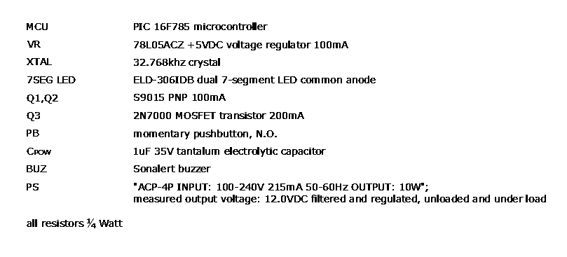
My objective in this design was to simply it as much as possible parts-wise--to minimize the number of discretes. The original design called for the use of MOSFET transistors exclusively to obviate the need for base resistors but I currently don't have any common cathode LED displays on hand and I need a timer ASAP so I had to use PNPs for the common anode display. There is only one pushbutton and it uses the weak pull-up of the MCU, hence a discrete pull-up resistor is unnecessary.
Features:
- Maximum time/readout = 99 minutes
- Display is shut down and MCU goes to sleep 10 seconds after readout becomes zero
- After timing has commenced readout flashes at a frequency of exactly 1Hz and with a duty cycle of 50%. Flashing readout is therefore counting down seconds.
- The pushbutton has multiple functions depending on status of the timer:
- when readout is on, pressing it for a fraction of a second increments readout by one. Keeping it depressed for half a second increments readout by 10 and keeps incrementing by 10 while pressed. No further readout change will occur when readout rolls over to zero. Button must be released and depressed again to increment again.
- when readout is off (MCU is in sleep mode) button acts to wake up the MCU.
- when timer has begun countdown but has not yet reached zero, button acts to abort timing.
- when timer has counted down to zero and buzzer alert is sounding, button acts to stop the buzzer
Detailed description of timer operation and its firmware:
Upon power up, the MCU will be in Standby mode and 2-digit seven-segment LED display will read 0. If PB is momentarily pressed a 7ms beep will sound and the LED display will read 1. Because of the limitations of the display, the maximum number of minutes the system will accommodate is 99 minutes.
After the first keypress (unless it was to awaken the MCU) firmware enters Userinputting mode. Further momentary presses of PB will increment the time by one and a 7ms beep will sound and time will be displayed. Keeping PB depressed for about half a second will increment time by 10 minutes. If time displayed is not a multiple of ten (ie., dividing by ten will result in a remainder), then keeping PB pressed will change time to the next nearest higher multiple of 10. Eg. If current time displayed = 8 then it will be changed to 10. If display = 24 then it will be changed to 30. If PB is kept depressed, increment by 10 will continue until the key is released or until time increments to 0 (there is no 100). A 7ms beep will sound every time heating time is incremented/decremented by 10.
If time displayed is not zero then after no button presses are made for approx 3 seconds from the last button press, countdown will begin and four sets of 50ms beep followed by 50ms silence will sound to indicate that countdown has commenced. Firmware is now in Countingdown mode. The amount of time left will be displayed and display will flash once every second. When time is down to 1 minute, display will change from displaying minutes to seconds. Thus at one minute it will display "60" meaning 60 seconds. Display will cease flashing. Pressing either button while in Countingdown mode will abort countdown and a 7ms beep will sound. Firmware is then returned to Standby mode.
When countdown time has elapsed firmware is changed to Countdownfinished mode. 3 alarm sequences are sounded in succession: 10 sets of 0.1sec beep + 2sec silence, 10 sets of 0.25sec beep + 1.25sec silence, continuous 0.5sec beep + 0.5sec silence. At any time when firmware is in Countdownfinished mode, any button press will terminate the alarm and firmware will be switched back to Standby mode.
When in Standby mode and no button presses are received in approx 10 seconds, LED display is turned off and the MCU goes to sleep. It can be awakened by a button press. The button press that awakes the MCU does not count as time input--the reading is zero when the MCU wakes up. No beep is sounded when a button press wakes up the MCU.
Timer0 is set up to overflow every 8ms. In main() timer0 interrupt flag is continually polled. When it gets set, the input button is checked by the switch debounce routine. This routine determines whether the switch is bouncing or not, and if not whether it is at a high/low level and whether or not a falling/rising edge has occured. A falling edge indicates a valid button press. The routine also keeps track of how long the button has remained pressed and how long it has remained not pressed.
Timer1 is used for countdown timing. Timer1 uses an external 32.768kHz crystal for its clock. With a prescale set to 1:1, TMR1L = 0, and TMR1H set to 192, timer1 overflows every 256 * 64 / 32768 = 0.5sec. Timer1 is turned on only when countdown commences and is stopped after countdown or an aborted countdown.
Firmware uses a state machine implemented using switch()/case statement. There are four possible states: Standby, Userinputting, Countingdown, and Countdownfinished. Upon power up state = Standby. After any button press state changes over to Userinputting. Should countdown commence state changes to Countingdown. Should inputting be canceled states changes to Standby. Upon completion of countdown state changes over to Countdownfinished. When a button is pressed to stop alarm state changes to Standby.
The two digits of the seven segment display are multiplexed and each digit is turned on every time timer0 overflows (8ms). Thus, the refresh rate is 62.5Hz. Because of display flickering problem button beep should be less than timer0 overflow period. When longer beeps are required (eg. to indicate countdown has ended) a state machine implementation (employing switch()/case statement) is used within the main state machine.
Watchdog timer is enabled when MCU is awake and disabled when it goes to sleep. PORTA pull up for input button is enabled. Button is debounced in software. When MCU goes to sleep interrupt-on-change is enabled to allow button press to wake up the MCU. Upon waking IOC is disabled.
Wednesday, January 5, 2011
555 propagation delay
Still using the same 555-relay circuit I did a "prequel" and monitored the propagation delay between S(et)-R(eset) inputs and 555 output state change. Channel 1 of oscilloscope was connected to either pin2 or pin6 of the 555, while channel two was connected to pin3. Ground clips were connected to circuit ground. Trigger mode was of course single sweep, rising or falling edge triggered, and triggering on channel 1. Trigger voltage was adjusted accordingly depending on whether rising or falling edge trigger was selected. Each screenshot below is a different, unique acquisition.
The switch used for S and R were simply short lengths of AWG#22 solid wire. One end was plugged into the breadboard slot for pin2/pin6 and the other end was momentarily plugged into the ground/VCC slot when the 555 was to be triggered. What amazed me--and as you will see in the shots below--was that there was no contact bounce at all with this most primitive method of switching.
A. Channel 1: 555 pin2, falling edge trigger.
Propagation delay, measured @50% of VCC: ~200ns


B. Channel 1: 555 pin6, rising edge trigger
Propagation delay, measured @50% of VCC: ~175ns


Interestingly, there's very noticeable ringing when pin3 goes from high to low. And it begins the moment pin6 goes high. Quite intriguing. Wonder what's happening internally.
All of the tests above were done with the 2N7000 and relay connected. They were disconnected from the circuit and the results were still the same including the observed pin3 ringing.
The switch used for S and R were simply short lengths of AWG#22 solid wire. One end was plugged into the breadboard slot for pin2/pin6 and the other end was momentarily plugged into the ground/VCC slot when the 555 was to be triggered. What amazed me--and as you will see in the shots below--was that there was no contact bounce at all with this most primitive method of switching.
A. Channel 1: 555 pin2, falling edge trigger.
Propagation delay, measured @50% of VCC: ~200ns


B. Channel 1: 555 pin6, rising edge trigger
Propagation delay, measured @50% of VCC: ~175ns


Interestingly, there's very noticeable ringing when pin3 goes from high to low. And it begins the moment pin6 goes high. Quite intriguing. Wonder what's happening internally.
All of the tests above were done with the 2N7000 and relay connected. They were disconnected from the circuit and the results were still the same including the observed pin3 ringing.
Tuesday, January 4, 2011
Propagation delay of 555-relay circuit
Given that the relay contact bounce test circuit is still on the breadboard I recorded the time delay between 555 pin3 level change and relay NC/NO contacts state change. Using that very same circuit without any modification, I connected channel 1 probe to 555 pin3 and channel 2 probe to VO. Ground clips of both channels are connected to circuit ground. Channel 1 is set to 2V/div while channel 2 is at 5V/div--so that the two waveforms don't overlap one another on the screen. Trigger is set to single sweep, edge triggering on channel 1. Each screenshot below is a unique acquisition.
A. 555 pin 3 output rising, NO contacts closing. Time delay ~10.5ms (excluding contact bounce, i.e. delay is measured from 555 pin 3 rising edge to the very first falling edge of NO contacts)


B. 555 pin 3 output falling, NO contacts opening. Time delay ~8.6ms


C. 555 pin 3 output rising, NC contacts opening. Time delay ~7.3ms


D. 555 pin 3 output falling, NC contacts closing, Time delay ~12.2ms (excluding contact bounce)


A. 555 pin 3 output rising, NO contacts closing. Time delay ~10.5ms (excluding contact bounce, i.e. delay is measured from 555 pin 3 rising edge to the very first falling edge of NO contacts)


B. 555 pin 3 output falling, NO contacts opening. Time delay ~8.6ms


C. 555 pin 3 output rising, NC contacts opening. Time delay ~7.3ms


D. 555 pin 3 output falling, NC contacts closing, Time delay ~12.2ms (excluding contact bounce)


Relay contact bounce test
I haven't really tested the contact bounce characteristics of any mechanical switch so I thought I'd use an oscilloscope to check those of an electromagnetic relay. I picked the Telemecanique RXM2AB2JD mini relay with a 12VDC coil since I like that relay for its smart design and have a couple of them in stock.
Now we can't just use a mechanical switch to directly turn the relay on and off since that switch would itself have contact bounce. We need to switch the relay with a near perfect square wave. To make things simple I opted to use a 555 to perform this switching. I wired the 555 as a simple RS latch (flip flop) thus turning the 555 into a switch debouncer. So now we can use the any mechanical switch and the output of the 555 should, at least theoretically, be a clean, crisp, bounce-free square wave. Here's the debouncing circuit which I assembled on a solderless breadboard:
 You will notice that pin2 is normally high while pin6 is normally low. When S(et) is pressed momentarily pin2 goes low and pin3 goes high and stays high. When R(eset) is momentarily pressed pin3 goes low and stays low.
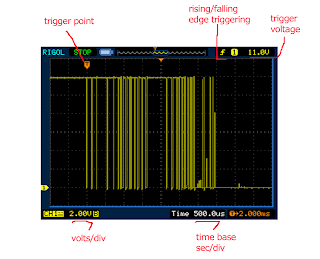
Before showing the oscilloscope readings here's a guide to reading the Rigol DS1102E screen display.
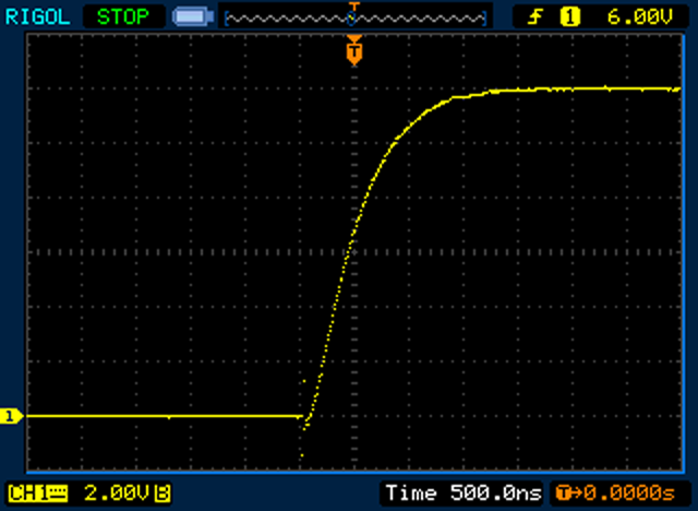
 I tested the 555 output (pin 3) to make sure that I was getting a nice clean square wave. The following screenshot is a typical of what I got. As can be seen rise time is around 200ns while fall time is some 10x shorter.The oscilloscope was set to display dots (so we can see if sufficient samples were taken during the rise and fall).


I don't want the 555 getting loaded down by the moderately high current draw (~75mA @12VDC) of the relay so I used a 2N7000 MOSFET transistor to switch the relay coil. I checked the rise and fall times of 2N7000 as well just to make sure, so before installing the relay I connected a 10Kohm pull-up resistor to the transistor drain:
 Here's the input-output voltage response diagram for the above circuits (555 with and without the 2N7000):
 And here are the oscilloscope readings for VO (voltage at transistor drain with respect to ground):


Below are the final test circuits with the relay and its normally open (NO) and normally closed (NC) contacts used for testing relay contact bounce. Star connections were used for VCC and ground to try and isolate the control circuitry from relay coil noise produced during energization/de-energization.

 The input-output response diagram:

The following screenshots show the voltage across the relay when it is switched on. Take note of the different time base of each shot. Each of them is a different acquisition (i.e., relay is switched off then turned on again for each screenshot). Ringing is conspicuous.


Below are screenshots showing the voltage across the relay when it is switched off. Again, take note of the different time bases of each shot, each of which is a different acquisition. Note as well that the vertical division is now 5VD/div in order to get all the data points on screen. As with turn-on ringing is evident.


In the following shot I wanted to show more detail of the relay voltage as it de-energizes so I decreased the vertical division to 2V/div. Time base is 100ns/div.

And finally, here are oscilloscope readings for the relay contact bounce.
A. Normally open contacts
1. N.O. contacts closing. For each the three acquisitions the waveform is presented first as a vector and followed by a screenshot showing it as dots. Note the differing time bases.


The following two shots are from the above 20µs acquisition. I merely dialed the time base up to 100µs (and hence we see the waveform is truncated at the right as the scope's sampling memory has been used up).


2. N.O. contacts opening. For each of the two acquisitions the waveform is presented first as a vector followed by a screenshot showing it as dots. Time base for both acquisitions is 20µs.


B. Normally closed contacts
1. N.O. contacts opening. For each of the three acquisitions the waveform is presented first as a vector followed by a screenshot showing it as dots. Note the differing time bases.


B. NC contacts closing. For each of the three acquisitions the waveform is presented first as a vector followed by a screenshot showing it as dots. The first three acquisitions have a time base of 500µs/div; the last two 50µs/div.


Summary
Contact bounce is clearly evident when the NO and NC contacts are closing, with the contacts closing and opening for many cycles before settling down to a steady closed position. From the readings above NO contact bounce period is from 2 to 2.5ms, while NC bounce is from 3 to 3.25ms. Compared to manual switches which may take tens of milliseconds to settle, contact bounce period of this relay is short.
NC contacts do not exhibit any bounce at all when opening. It's amazingly clean. NO contacts, however, show an interesting characteristic. There seems to be a short period (tens of microseconds to around 200ms) of high resistance--voltage across the contact (with reference to ground) hovers at around 3V. The resistance can be computed using the voltage divider rule for resistances in series.
Let
VS = voltage source = 12V
R1 = 10Kohm resistor
R2 = NO contact resistance
VR2 = voltage across R2
VR2 = R2VS / (R1 + R2)
Solving for R2 we obtain:
R2 = (VR2R1) / (VS - VR2)
Plugging in the values we obtain R2 = 3.3Kohms
One possible reason for the difference in contact opening characteristic between NO and NC contacts is that NO opens under spring force while NC opens upon coil energization--the latter probably applies a much greater force than the spring thus greatly minimizing contact "sticking." Another reason could be arcing across the contacts while they're opening which is relatively slow under spring force. Contact opening characteristics will need to be further examined under higher voltages and currents.
Now we can't just use a mechanical switch to directly turn the relay on and off since that switch would itself have contact bounce. We need to switch the relay with a near perfect square wave. To make things simple I opted to use a 555 to perform this switching. I wired the 555 as a simple RS latch (flip flop) thus turning the 555 into a switch debouncer. So now we can use the any mechanical switch and the output of the 555 should, at least theoretically, be a clean, crisp, bounce-free square wave. Here's the debouncing circuit which I assembled on a solderless breadboard:

Before showing the oscilloscope readings here's a guide to reading the Rigol DS1102E screen display.


I don't want the 555 getting loaded down by the moderately high current draw (~75mA @12VDC) of the relay so I used a 2N7000 MOSFET transistor to switch the relay coil. I checked the rise and fall times of 2N7000 as well just to make sure, so before installing the relay I connected a 10Kohm pull-up resistor to the transistor drain:


Below are the final test circuits with the relay and its normally open (NO) and normally closed (NC) contacts used for testing relay contact bounce. Star connections were used for VCC and ground to try and isolate the control circuitry from relay coil noise produced during energization/de-energization.


The following screenshots show the voltage across the relay when it is switched on. Take note of the different time base of each shot. Each of them is a different acquisition (i.e., relay is switched off then turned on again for each screenshot). Ringing is conspicuous.


Below are screenshots showing the voltage across the relay when it is switched off. Again, take note of the different time bases of each shot, each of which is a different acquisition. Note as well that the vertical division is now 5VD/div in order to get all the data points on screen. As with turn-on ringing is evident.


In the following shot I wanted to show more detail of the relay voltage as it de-energizes so I decreased the vertical division to 2V/div. Time base is 100ns/div.

And finally, here are oscilloscope readings for the relay contact bounce.
A. Normally open contacts
1. N.O. contacts closing. For each the three acquisitions the waveform is presented first as a vector and followed by a screenshot showing it as dots. Note the differing time bases.


The following two shots are from the above 20µs acquisition. I merely dialed the time base up to 100µs (and hence we see the waveform is truncated at the right as the scope's sampling memory has been used up).
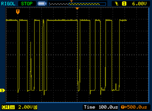

2. N.O. contacts opening. For each of the two acquisitions the waveform is presented first as a vector followed by a screenshot showing it as dots. Time base for both acquisitions is 20µs.


B. Normally closed contacts
1. N.O. contacts opening. For each of the three acquisitions the waveform is presented first as a vector followed by a screenshot showing it as dots. Note the differing time bases.


B. NC contacts closing. For each of the three acquisitions the waveform is presented first as a vector followed by a screenshot showing it as dots. The first three acquisitions have a time base of 500µs/div; the last two 50µs/div.


Summary
Contact bounce is clearly evident when the NO and NC contacts are closing, with the contacts closing and opening for many cycles before settling down to a steady closed position. From the readings above NO contact bounce period is from 2 to 2.5ms, while NC bounce is from 3 to 3.25ms. Compared to manual switches which may take tens of milliseconds to settle, contact bounce period of this relay is short.
NC contacts do not exhibit any bounce at all when opening. It's amazingly clean. NO contacts, however, show an interesting characteristic. There seems to be a short period (tens of microseconds to around 200ms) of high resistance--voltage across the contact (with reference to ground) hovers at around 3V. The resistance can be computed using the voltage divider rule for resistances in series.
Let
VS = voltage source = 12V
R1 = 10Kohm resistor
R2 = NO contact resistance
VR2 = voltage across R2
VR2 = R2VS / (R1 + R2)
Solving for R2 we obtain:
R2 = (VR2R1) / (VS - VR2)
Plugging in the values we obtain R2 = 3.3Kohms
One possible reason for the difference in contact opening characteristic between NO and NC contacts is that NO opens under spring force while NC opens upon coil energization--the latter probably applies a much greater force than the spring thus greatly minimizing contact "sticking." Another reason could be arcing across the contacts while they're opening which is relatively slow under spring force. Contact opening characteristics will need to be further examined under higher voltages and currents.
Subscribe to:
Posts (Atom)