Monday, December 28, 2009

When not to use a clamp meter

Was just wondering whether my hardly-used Sanwa DCM 60L clamp meter would be able to measure the current draw of an incandescent lamp. I tried it out on a 60Watt bulb, and to my surprise the meter reading remained at 0.0A. Odd, I thought. I then tested a 100Watt. The meter budged by one count and read 0.1A. Obviously the meter was incorrect in the first case, since the bulb was shining brightly. And unless the lamp was way out of spec, the meter was wrong in the second case as well.

To find out the real deal, I decided to determine current using the Sanwa CD771 multimeter. I placed a 10-ohm, 5%, 1-Watt resistor in series with the bulb (the lamp socket, that is, in my test rig) via a terminal block onto which I screwed in the resistor leads and the wires to make a good and safe connection. The ohmmeter measured the actual resistance to be 9.5 ohms.

I would've wanted a smaller resistor value so that it would be insignificant compared to the lamps' filament resistance. Unfortunately I don't have any resistor smaller than 10 ohms and I don't have any other 10-ohm resistor (which I could connect in parallel). So I had to make do with this one resistor even if according to my calculations it would burn out if I used a 100-Watt lamp in the circuit: [(100W/220V)2]10Ω = 2.1Watts.

What's with the resistor anyway? I want to find out the actual current going through the circuit. To accomplish that I would measure the voltage drop across the resistor. It would then be trivial to compute for the current through the resistor and, because this is a series circuit, that would be the same current through the lamp as well.

The results are in the table below. Measured voltage of the mains at the time of testing was 232 Volts. This is the value used for calculations in the last column.


Lamp TypeClamp meter reading (without resistor)Voltage Drop across Resistor (V)Computed Current (A)Computed Total Power Dissipation (W)
Philips Softone 60Watts0.02.590.2762.6
Philips Spotline R80 60Watts0.02.570.2762.6
Philips Superlux 100Watts0.14.310.45104.4


As can be seen above, the lamps are in fact very close to their specified output and it was the clamp meter that was way, way off the mark. But why? I read the manual again and it turns out that at 50-60Hz the meter's accuracy is +/-(2% + 5 counts) and at 60-500Hz it's +/-(2.9% + 5 counts). These are for currents <200A.

Since the reading can be off by 5 digits (in this case that translates to +/- 0.5A), this clamp meter is absolutely useless for measuring currents less than 1A. Even for a current of 1A this meter will show anywhere from 0.4 to 1.5A. Thus the reading can be off from the true value by -60% to +50%. For 10A, reading will be in the range of 9.2 to 10.7A, which translates to -8% to +7% accuracy. Tolerable. In the 200A range, the meter reaches its highest accuracy of +/- 2 to 2.9% when measuring currents just below 200A. At over 100A the +/-0.5A (which is what the +/- 5 counts means in this range) becomes negligible.

So now I must remind myself that with this particular meter I have to take with a grain of salt any reading below 10A. Given the 220VAC mains voltage here, finding out the current draw of a load less than 2000W simply isn't worth checking with this meter.

Saturday, December 26, 2009

Twinkle, twinkle little bulbs, how I wonder how you're powered

Been meaning to find out the design of commercial Christmas lights control units. Obviously a microcontroller takes care of the various flashing patterns, frequency, fading in and out, etc. I was at a loss, however, at how they power the MCU--a low voltage DC device--and what they use to power the lamps--AC or DC.

Got the chance to do that when I fortuitously came across some old strings of lights that my brother had left here about a year or so ago. I didn't even know he had left them. I was clearing some stuff and stumbled upon them.

This particular set has three wires coming out of the control box. It was evident that one was a common and the two other were strings of bulbs. A momentary contact switch allows the user to cycle through the six or eight lighting/flashing patterns.

I was smiling when I saw two screws on the small control case. That meant I could actually open the thing up without cracking the case to bits. I would've been rather reluctant to ruin the plastic enclosure had it been glued shut.

I promptly opened the case and to my surprise the board contained very few parts. Take a look (click to see a larger version):


Seeing the four diodes immediately told me that the circuit uses a bridge rectifier. The electrolytic capacitor must be for filtering, I mused. And the two TO-92 parts just had to be transistors to switch the two lines of bulbs. The MCU is on the vertical daughterboard, the die sealed in a blob of black epoxy.

What intrigued me was how the MCU was being powered. At first I thought that the two resistors might be forming a voltage divider and feeding the MCU with a low voltage DC which is then filtered by the cap. But when I took the multimeter, traced the connections, and actually drew out the circuit, it turns out this simply was not so.


I now believe that the MCU has an integral shunt regulator or a voltage regulator of some sort which automatically delivers the required MCU voltage, probably 5V. The 180K resistor is necessary in order to drop practically all 200VDC across it (VACrms × √2 × 0.636 = VDC average). The 10uF capacitor filters the pulsating DC. Its 63V rating implies that voltage at the MCU's VDD pin is well below the raw rectified voltage of 200VDC (with a peak of >300V). That the resistor value is 180K means that average current going through is tiny--200V/180K = 1.1mA. The MCU has to be using a relatively low clock frequency and the load--the two transistors--have to be drawing a miniscule current.

Since I see no crystal, resonator, or resistor-capacitor to serve as clock, the MCU is probably using an internal oscillator. Stands to reason since this is a low-priced product. The board has provisions for 4 transistors and thus 4 branches of lights but only two are installed. Counting all the connections to the MCU including the provision for two more transistors, I surmise that this is an 8-pin type. Since the lighting pattern chosen by the user via the tactile switch is remembered even after the unit had been turned off, the MCU must be storing the value in nonvolatile memory, probably EEPROM.

Interestingly the 2-Mohm resistor is connected to the 220VAC line. The other end meanwhile goes directly to one of the MCU's pins. This must imply that the zero crossing of the AC wave is being sensed. Why would the circuit be doing that? It probably uses zero crossing for pulse width modulation timing purposes. Among the patterns available in this set of lights is a gradual fade in/out. Given the components, without a doubt PWM is being used to achieve this. I imagine that the PWM frequency is 120Hz--synchronized to the power line--while the duty cycle is varied from 100 to % (and back to 100%) when the lights are being dimmed and brought back to full brightness. Whenever a zero crossing is detected, the transistor is switched on. For how long depends on the duty cycle as determined by the firmware. How fast the duty cycle is incremented/decremented is variable--again as determined by firmware.

Since the load is being powered by full-wave rectified and unfiltered AC, the PWM system is analogous to AC phase control. Had this been an AC system, the MCU would, upon detection of zero crossing, begin timing. After a computed delay time, it would pulse the triac briefly to turn it on. The triac would then conduct until the next zero crossing upon which it automatically turns off and switches to high impedance state.

In this all-DC system, transistors are used for switching. Although I drew NPN BJTs in the above schematic, there is a good chance that MOSFETs are being used since they draw very little current. And as you may have noticed there are no current limiting resistors to the base of the transistors. I googled the printed part number "1225 A868" but couldn't find any useful information on it. What we do know is that these transistors are high voltage types since >300V peak will be across their output terminals.

Saturday, December 19, 2009

ATX in AT's clothing

I was going to use a very old AT power supply and convert it into a bench power supply, the reason being that it has a much larger case than an ATX which means there would be ample space for the seven binding posts I intend to install (five voltages and two ground). Moreover, it has an integral AC power switch right on the case--something you no longer get in current power supplies (and in some AT's the switch is not on the case but on the front panel of the computer). So this enclosure is perfect.

Alas, a check of the voltage outputs revealed that while the +5VDC line was fine, its +12VDC was only delivering 10.8V even when two hard drives were plugged in and whirring away. This was rather disappointing since a 10% deviation is simply unacceptable. But I really want this enclosure.

To cut to the chase I found an ATX power supply from a discarded Pentium 3 computer which showed output (positive) voltages within 5% of their stated values. After mulling it over I decided to disembowel the AT and transplant the ATX board into it.

Testing the ATX I discovered that while even without a load the PS starts (fan spins) and outputs were live, without any load the outputs were not too good: +5.25VDC and +11.5VDC. These two voltages are the most important to me so they're the ones I use as benchmark. I further discovered that loading the 12VDC line did not improve its output. But loading the 5VDC line not only pushed that output down toward 5.0VDC, but also pulled up the 12VDC line toward 12.0V.

My main reference for this project is How to Convert a Computer ATX Power Supply to a Lab Power Supply. In that article it advises using a power resistor to load the output. I thought, Why waste all that good power? Why not put it to some use? As in lighting up a bank of LEDs. I initially thought of using white LEDs that would be configured into some sort of a lamp to illuminate whatever circuit the PS was powering. However, I decided to illuminate the interior of the enclosure instead, using colored LEDs to bathe the components inside in theatrical lighting.

The AT has a 110/220VAC switch. Right above that is the socket into which the computer monitor's power cable is plugged. This area would be perfect and large enough for a small prototyping board with all the LEDs mounted on it. So I removed both the switch and socket. I cut a board down to a size that would fit that space. I then populated it with a total of 8 red and 10 blue LEDs. Supply is 5VDC and resistors were chosen such that current is about 15mA per branch. Measured forward voltage of the red LEDs were 1.8 and so two reds are in series per branch with a 100-ohm resistor as current limiter. Blues have a forward voltage of 3.0V and so there's only one LED per branch in line a 150-ohm resistor. There are 14 branches and so total current is around 210mA, for a total power dissipation of around 1000mW. Test shows that with this load, output voltages are as follows:


Ideal output (volts)Actual output (volts)
-12-10.76
-5-4.77
+3.3+3.32
+5+5.17
+12+11.96


The green and a black wire are connected to a switch at the back. When green is not connected to ground PS is virtually off including the cooling fan. When green wire is grounded PS supplies power to the outputs. The AC power switch has to be closed of course. Purple and gray wires ("standby" and "power-good", respectively) are not used and not connected to anything.


Here's the ATX board and its fan already installed in the AT enclosure. The connectors to the motherboard and drives have all been snipped off and I've bundled and temporarily taped the wires by color (voltage). The bunch of red-black-yellow wires on the right is for the LEDs. I initially was going to use the +12V (yellow) but then as I said above tests showed that using it does not contribute to +12V output regulation. This yellow wire eventually joined its siblings.


Here it is after the case cover had been drilled and the binding posts installed. I couldn't find any other colors besides red and black so I used red binding posts for the negative voltages as well. Notice there are two posts for ground.


Back view showing the AC power switch and the PS-ON switch. The reason for the latter's location is that there already was a 1/8" hole on that spot. I just made it larger. The "AMAX" plastic sticker nameplate is from the ATX. You can see that the power supply was made in 2000. The neat thing about this PS is that it actually lists the wire color codes.


A look inside the connections to the binding posts. All wires were terminated with ring lugs. Even if the nuts come loose the wires won't fall onto the board and possibly cause disaster.


A view from the fan side. You can see the rectangular holes where the the monitor power socket and 220/110V selector switch once were. Because the copper side of the prototyping board will be exposed and accessible through these holes, I mounted an aluminum sheet to seal them. The sheet is sandwiched between the casing the two standoffs for the board.


The prototyping board is clearly visible. The top two rows are red LEDs. The rest are blue. I ran out of diffused epoxy blue LEDs so most of them are the clear type.


And the LEDs are shining!


The following were taken in complete darkness. Even with 18 LEDs the total output is nowhere close to bright.

Wednesday, December 16, 2009

It's the season ... to automate

I don't celebrate Christmas but when there's an electronics design opportunity in it I don't complain. There are these Christmas lights which I have to switch on at night and then switch off before midnight. This is a nightly task which will go on till the end of the year. Well, as can be expected there are times when I'm not around to turn the lights on and there are days when I simply forget. And there has been at least one occasion when I forgot to unplug the lights from the outlet (that's what serves as the switch).

Got fed up so I decided to automate it. What I needed was for the circuit to know it's dusk, turn the lights on, keep them lit for several hours, and then have them off until dusk the next day. This is a temporary circuit--one month and it won't be used anymore--so I decided to just keep everything on a breadboard. I also decided that it would be best to keep the main electronics indoors with only the "dusk sensor" somewhere outdoors.

In a nutshell this is how the circuit works. The dusk sensor outputs an analog voltage proportional to the ambient light level. This is fed to a microntroller which switches the load when light level falls below a value determined by the user. After a preset time duration the MCU turns off the load.

The sensor is a simple voltage divider using an LDR and a 300K resistor. Its output is fed to an op amp configured as a voltage follower. The ultra high impedance of this buffer prevents any loading of the signal. The op amp output is then sent to one of the MCU's analog input channels. The analog signal gets digitized by its ADC. The MCU compares this value with the trip level selected by the user. The trip level is adjusted using a 10K potentiometer whose output is connected to another of the MCU's analog channel.

I've chosen an 8-pin Microchip PIC12F615 because the circuit needs only two inputs and one output and I need those inputs to be analog channels. I could've picked one from the PIC10F series but I don't have software to program those in C. I'm just not in the mood right now for assembly language. I have about half a dozen models of single-supply, rail-to-rail Microchip op amps around here. I just opted for the MCP6273.

Because there may be abrupt and transient changes in ambient light level (lightning flash, car headlamp glare, prankster shining a flashlight, etc.) it is necessary to make sure that the sensor/circuit ignores these changes, else intermittent switching of the load occurs. This can be done via hardware by adding a few components--a capacitor, diode, and maybe a resistor. It can also be effected in firmware. The latter is what I opted for--why put to waste all that MCU computing power and memory?

I developed an algorithm for this two years ago and is based on moving averages. Readings are taken at fixed intervals (one to several seconds apart--the longer the interval the more immune to transient changes in light level). Each reading is compared to the previous average. If it exceeds the average by a predetermined amount (meaning there has been an abrupt change in light level) this reading is replaced with the average plus or minus the maximum allowed change (added or subtracted depending on whether the light level has increased or decreased). Thereafter, the last eight readings are averaged and compared to the trip level. If this new average is below the trip level then the MCU turns the load on. A hysteresis value (deadband) is incorporated such that the average light reading must increase beyond the trip level + hysteresis before the firmware resets a flag bit which keeps track of the transition from light to dark and dark to light (analogous to the rising/falling edges of a square wave). If the light level is between the trip level and trip level + hysteresis, then no action is taken.

Power supply is an adapter from my collection of old chargers, adapters, and the like. The one I found suitable is an Ericsson phone charger. It's probably a linear supply--cubelike and heavy, implying a bulky transformer. Its output is around 5.3VDC which drops to around 4.5V when the gas guzzling DC relay (40-ohm coil) is connected. I didn't even bother using an oscilloscope to check ripple voltage. I just used the multimeter to see what the DC voltage was with and without the load. To help Ericsson along I added a 1000uF 10V filter cap. This pulled up the with-load DC to 4.8V. Fortunately the relay still functions at barely 5VDC this adapter outputs. A diode (D1 in the schematic) was placed in series to drop the supply to the chips to <5VDC just to make sure they'll be operating within their supply limits.

The MOSFET transistor I used to switch the relay is a 2N7000. Relay is an Idec 4PDT. Coil: 6VDC, 40-ohms. Contacts: 250VAC 6A. It's plugged into a socket so all the AC and DC wires can be conveniently screwed in and safely secured. I added LEDs to provide visual indicators for the status of the load. A high efficiency blue LED that requires only a couple of milliamps to be visible was used to indicate "on." This choice was made in order to reduce the total current load on the power supply when the relay is on.

The main breadboard and relay were plunked into a plastic box. The sensor was also put in its own small translucent box and situated outdoors some 10 meters from the main electronics. So far so good. I adjusted the potentiometer so the load turns on when the streetlights have already been on for some 15 to 30minutes. The circuit works as required and the MCU timer is right on the money, turning the load off in almost exactly 5 hours even if it's only using its internal clock oscillator.

I love these tiny microcontrollers.


Click on the schematic.

Thursday, December 10, 2009

Telephone signals

Took the Rigol DS1102E scope and connected the probe to my home telephone line. I obtained the following readings. Click on the image to see a more legible version. Do keep in mind that dial tone, ringing, busy tone, and off-hook warning frequencies (and cadences) vary from country to country. So do voltages and other parameters. Seems like a free for all.

1. On-hook, telephone on standby. When the phone is not being used, the line is at 48 volts DC.


2. On-hook, phone ringing.


In the screen shot above the cursors are on and I've adjusted them to measure the DC voltage right before the ringing signal. You can see at the top right inset (delta Y) that the voltage has jumped to 54 Volts right before ringing.

The amplitude of the ringing signal itself is shown below measured. The value (delta Y) is 132 Volts peak to peak. That's around 47 Volts RMS (132/2/√2) riding on top of the 50 or so Volts DC.


I switched to split screen mode and both ringing signal and its frequency spectrum as obtained through the fast Fourier transform (FFT) function are shown below.


The same in full screen mode:


As you can see cursor A reads 20.8Hz. That's the ringing signal frequency


3. Off-hook, dial tone:


Like the ringing signal the dial tone is also a sine wave, but this one has high frequency noise riding on it. The cursors are on and you can read off the peak-to-peak amplitude which is around 350mV. The FFT function was turned on when I took the above reading and it is shown below.


I changed the resolution from 500Hz to 50Hz per division to get a better view of the peak frequency:


The dial tone is basically a single tone at 420Hz, although during other times I've measured it at 440 to 450Hz. The drift could be at the telephone company's end or somewhere along the transmission.


4. Off-hook, busy signal. I picked up the phone and just waited until the dial tone gave way to the busy signal. That took several seconds. Here's the waveform I got.


The low level high frequency noise to the left of the busy signal is the lull between the busy tone pulses. The purple curve at the bottom half is the frequency spectrum provided by the FFT. You can already see three or four significant blips there. Below are measurements of those frequencies using the cursors.


And a more detailed look at those:


So what I got were prominent signals at 480Hz and 620Hz with smaller signals at 1.9KHz and 2.0KHz. The latter two may or may not be actual components of the busy signal.


5. Off-hook alert. After several more seconds the busy signal gives way to the loud off-hook warning tone, which is screaming, "Hang up, you idiot!"


As you can see the maximum peak-to-peak voltage is approximately 460mV. The waveform along with the frequency spectrum:


Frequency spectrum measurements:


A closer look at those frequencies:


The most significant frequencies are 1.4KHz and 1.8KHz. The amplitudes of the 2.0, 3.2 and 3.6KHz are rather small. These may or may not be part of the off-hook alert signal.

Wednesday, December 9, 2009

Minuteman computer and the Tektronix 465B

Jim Williams, electronics engineer and author of The Art and Science of Analog Circuit Design.

Thursday, July 23, 2009

Online lectures on electronics

Just stumbled on the following treasure. The National Programme on Technology Enhanced Learning (NPTEL) has hundreds of hours of recorded lectures on electronics and electrical engineering and other subjects as well. Watch them all on Youtube.

I just love lectures ... sans the exams of course.

Tuesday, June 30, 2009

You don't get what you don't pay for

Sigh. Repeat after me: You can't have your cake and eat it too. You can't have your cake and ....

I've been test driving the Hi-Tech C Pro compiler for the PIC MCUs and much as I am thrilled that it works under MPLAB and is being offered completely free (Lite version) without firmware size or time period restrictions, I must say that the lack of optimization in the freeware version is rather depressing. The code it produces is quite inefficient.

For instance, for the PIC 10F20x series, for the given a static global variable the C statement "POTATO++" or "++POTATO" is translated into assembly by Hi-Tech Lite as follows:

MOVLW 0x1
MOVWF 0x13
MOVF 0x13, W
ADDWF 0x1e, F

Am scratching my head. Why the two middle instructions? Why not cut to the chase and have:

MOVLW 0x1
ADDWF 0x1e, F

Or better yet, why not just

INCF 0x1e, F

Wasting two to three bytes and instruction cycles in an MCU that has only 256 / 512 words of program space is just crazy.

I know I'm making a hasty conclusion but this one example of utter wastefulness shows me why this is freeware. I'm wondering how the versions with "Omniscient Code Generation" will compile the above. Hopefully you do get what you pay for.

Monday, June 22, 2009

More on that timer

Modifications made to the timer:
  • New "wall wart" power supply. Oscilloscope test of output shows it has no filter capacitor so a 470uF 25V electrolytic was added to the board. No-load voltage with filter cap was >20VDC.
  • Added a LM78L12ACZ and LM78L05ACZ voltage regulator
  • A 1N4002 was added as a safety feature in case power supply polarity is inadvertently reversed.
Here's the schematic:


MCU = Microchip PIC 16F785
Q1,Q2 = S9012 PNP transistor
Q3 = 2N7000 MOSFET transistor
XTAL = 32.768kHz crystal
7SEG LED = ELD-306IDB dual 7-segment LED common anode
all resistors 1/4Watt 5%

I've installed the timer in my aunt's kitchen. Much to my chagrin the volume of the buzzer was not close to earsplitting. Although as with any sonalert buzzer, it will surely be heard tens of meters away.

Tuesday, June 16, 2009

The timer's dead; long live the timer!

Two years ago I installed a countdown timer at my sister's apartment. The user can set the time anywhere from 1 to 99 minutes. After the countdown is over a Sonalert buzzer will blare. The alarm has three stages, each with successively higher duty cycle. It begins with gentle fractional-second beeps so as not cause a heart attack. Each stage runs for approximately 10 seconds.

The engine that drives the timer is a 20-pin Microchip PIC 16F785 microcontroller. For user interface the time has a two-digit 7-segment LED display and two momentary contact buttons. Pressing the UP/DOWN button for a fraction of a second will increment/decrement the readout by one; keeping it depresed will increment/decrement the reading by 10. If the readout is not zero and no button is pressed for around 4 seconds, countdown begins. Once countdown has started either button will abort the count and readout will be zeroed. If countdown is allowed to run its course and the buzzer starts sounding, either button will turn the alarm off. When readout is "0" for some 16 seconds, readout will be blanked and MCU will go to sleep. Pressing either button will wake it up.

Although my sis has almost never used the timer (all that effort soldering the dang thing for nothing!) I just found out it doesn't work! The only reason I discovered it's on the blink is that I took it down and was going to give it to my aunt. She found out I have a timer in my home (practically the same design but has some improvements) and she says she needs one too.

To cut to the chase, it turns out the power supply is dead. The PSU is an Ericsson cell phone charger model AA21990 which has an output of 5.1V 450mA. To add to the trouble, while testing the timer using a working PSU (not an Ericsson) I discovered that the MCU was running very warm. Now that's bad! The timer was working fine, meaning the MCU was still running the firmware, but somehow or other there was a short or a quasi short somewhere. I inspected the solder side of the board but it was fine. I cleaned the board just to make sure. Finally in desperation I took out a new 16F785, burned in the firmware, and dropped it in the DIP socket. Well, what do you know? The original MCU was fried as well!

My guess is that the PSU must've taken the MCU with it when it burned out.

I tried reprogramming the MCU. This PICkit2 says it has a Vpp problem. At some point it couldn't even detect the device. Guess that's it for that chip. Its time is up!

I'm modifying the circuit before installing it in my aunt's home. Instead of being powered by 5VDC the buzzer will now be operated at 12 volts. That increases the alarm volume considerably so it can be heard even in the next room with the door closed. It's going to be earsplitting in the kitchen.

Monday, May 25, 2009

Firmware keeps an eye on the health of water level sensors

The sensor diagnostics routine I programmed into the water system I installed some two years ago finally paid off today. The alarm went off and the LEDs were flashing like crazy indicating that a sensor problem had been detected. For the particular fault that befell the system today, had there been no sensor diagnostics the tank wouldn't have filled to maximum. At most it would fill to 75%. And I wouldn't have known that a fault condition existed until I accidentally notice that the indicator LEDs aren't right.

Briefly, here's a description of the water system. There are two water tanks, one located at the ground level and the other at the roof deck of a two-storey house. Water from the mains fills the ground level tank (GT) via a solenoid valve whenever it's not full. The roof deck tank (RT) is normally filled by another solenoid valve, but when water pressure is insufficient to fill it within a predetermined amount of time then a pump kicks in to do the job. There are sensors in both tanks. Two types are employed. The primary sensors are simple stainless tubes of varying lengths to detect water at different levels of the tank. The other type of sensor is a float switch and is used to detect a full tank and tank overflow condition. The float has a magnet inside which closes a reed switch in the body of the assembly whenever it's buoyed up by water. For both tanks there are sensors for water levels of 25%, 50%, 75% and 100%. RT has an additional sensor to detect overflow condition (this is simply a float switch located above the 100% water level sensor).


Above is a stylized diagram and schematic of the sensor setup inside the roof deck tank. Pull up resistors (located in the control panel) mean that output is low when sensor is submerged in water.

The control panel is located adjacent to GT. The enclosure contains all of the electronics, actuator control circuitry (to switch the DC solenoid valves and 500-Watt AC pump), and power supply. It also has indicator LEDs arranged to mimic two bar graphs, indicating the water levels for each of the tank as well as LEDs for the status of the solenoid valves and pump. There are also LEDs for RT overflow condition and empty-tank condition for both GT and RT. A Sonalert buzzer provides the audible alarm.

MCU is a PIC16F627A. Sensor outputs from both tanks are filtered by a simple RC passive low pass filter before being fed to a 74AC540 octal inverting buffer whose outputs then drive both the LEDs and the input pins of the MCU.

I'll skip details of the other parts of the firmware and simply discuss the sensor diagnostics part. If I recall correctly, years ago before upgrading the circuit up to an MCU-based system there had been at least one instance when one of the gauge-24 wires to the stainless steel sensors snapped off. Can't remember what havoc that wreaked but it was a fault condition nevertheless that eventually had to be repaired. The diagnostics algorithm that's been included in the firmware is based on the fact that depending on the water level, there are combinations of sensors that are "on", so to speak, which are valid and some which are not. And by "on" here we mean that the sensor is submerged in water. The diagnostic routine simply checks whether the current combination of sensors that are on is valid. If it is then the program just continues. If the combination is invalid then the diagnostics routine keeps looping back and checking the sensors until the fault is corrected.

For instance when the 100% water level probe is on then obviously all the other sensors must be on too. If any are not then a sensor fault condition exists. So, if the 25, 50, and 100% water level sensors all purport to detect water but the 75% sensor doesn't, something must be wrong.

And that was precisely the fault condition this morning. Which led to the system automatically shutting off all the valves and pump and switching on audible and visual alarms which in turn sent me into panic mode. Given that the 75% level indicator LED for the upper tank was off while the 100% level LED was on, I jumped to the conclusion that it must be a loose or corroded connection. And I then proceeded to check the 75% level wiring and wire connections. Turned out I was wrong. It was in fact the 100% level sensor that was on the blink. And it wasn't even an electrical fault. The sensor is a float switch and apparently the float had become stuck--just slightly. Since the water level at that time was below the 75% sensor, the float actually dropped on its own while I was checking the stainless steel sensors. Algae or light mud could've been the culprit.

Wednesday, May 13, 2009

SIRCS: The real score

While researching the Sony SIRCS protocol (some say it's "SIRC") for infrared remote controls, I got somewhat confused as to the pulse widths for the ones and zeroes. You see some say that a zero is represented by a 0.8ms pulse width while a one is 1.2ms long, with a 0.4ms low between bits. On the other hand, there are others who say that it's 0.6ms and 1.2ms respectively with a 0.6ms space between bits. So who's right? Unfortunately Sony doesn't have an official online document on the protocol (or at least I haven't found one yet) to clear things up.

After more research, I've come to believe that it is in fact the latter that's correct--0.6ms for a zero and 1.2ms for a one. Let me just provide some references for this.

Jon Williams in his article "Creating Time-Lapse Video" in the March 2009 issue of Nuts and Volts writes: "The SIRCS signal has a 2.4 millisecond start bit, '1' bits are 1.2 milliseconds wide, and '0' bits are 0.6 milliseconds wide — and every bit is spaced by a 0.6 millisecond off-time."

Likewise, according to Microchip Application Note AN1064 entitled "IR Remote Control Transmitter" the SIRCS protocol has on time (bit period) of 1.2ms for a logical "1" and 0.6ms for a logical "0."

In his excellent site on infrared remote controls San Bergmans tells us that, "the pulse representing a logical '1' is a 1.2ms long burst of the 40kHz carrier, while the burst width for a logical '0' is 0.6ms long. All bursts are separated by a 0.6ms long space interval."

Finally, co-author Jack Smith, in PIC Microcontrollers: Know It All (Newnes, 2008) provides a waveform diagram for the SIRCS protocol, again showing that same bit periods.

Be that as it may, the three Sony IR remote controls that I've tested do in fact have on times of around 0.8ms to represent "0." I got 1.4ms for "1." I used a 38kHz IR receiver but the SIRCS operates with a 40kHz carrier frequency. That's a 5% difference. I don't know if that significantly affects the test results.

Sunday, May 3, 2009

Philips IR remote control

The only Philips IR remote control (IRRC) that I have is one for the 20PT3882 TV.


I needed to "see" the transmission of the above IRRC and measure the pulse widths. Unfortunately until recently I didn't have a digital oscilloscope to capture the very first transmission--the first packet. So I rigged up a PIC16F616 microcontroller and an LCD to display the pulse widths of the highs and lows. I used an Osram SFH5110-38 IR receiver (IRRX) to detect the IR signal (I don't have a 36kHz receiver so this Osram just had to do--I don't know how much this 5% difference impacts the results).

In a nutshell, I programmed the MCU to issue an interrupt every time the signal on the pin connected to the IRRX output changed state--high to low or low to high. One of the MCU timers is then used to measure how long the signal was high/low. This value is stored in memory. After all the bits have been collected, the pulse widths are sequentially displayed on the LCD.

I was not very confident that my setup would produce the desired results. To my relief, it actually worked well. When I aimed the IRRC at the IRRX and pressed a button, the LCD produced a stream of numbers (in microseconds/milliseconds) which corresponded to how long the pulses were high/low. The values I got were pretty much consistent with the Philips RC5 protocol, with short pulse widths of 0.800 to 0.944ms and long pulse widths of 1.712 to 1.840ms. The protocol says it should be 0.889ms and 1.778ms respectively.

I tested the digit buttons and they conformed to the protocol pretty well.

But I was confounded when I tried the cursor keys (the four blue buttons in the photo above). The LCD started spewing rubbish. Some long pulses were over 2.5ms long and some short ones were less than 0.5ms. Something was not right. Either this unit was not using the RC5 protocol (which I doubt) or my MCU setup was misreading the signals.

With the DSO I've finally put to rest my doubts about whether the transmissions were being faithfully rendered by the MCU. True enough at times pulse widths were off by over 30% or even 50%. I really don't know if this particular unit is a lemon or what.

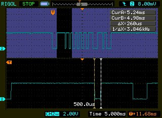
Here are some examples of out of spec pulses when the cursor keys are pressed. The pulse train on the upper half of each picture is one IR transmission (one packet). The lower half shows a zoomed-in portion. Vertical lines on the lower half are the DSO's cursors. You can read off the deltaX at the upper right. That's the measured pulse width.


The two pictures above are of the same transmission. I just moved the cursors. The two pictures below are from another transmission. Again, I moved the cursor lines.


Apparently, the very long pulse width (happens when IRRX output is high) occurs most frequently when the IRRC is within a meter of the IRRX. The closer the IR transmitter is to the receiver the greater the distortion in the received signal. At greater distances it seldom if ever occurs. The very short pulse widths (happens when IRRX output is low) seems to occur at whatever distance.


For info on the Philip's RC5 protocol see:

AN10210 Using the Philips 87LPC76x microcontroller as a remote control transmitter

AN1064 IR Remote Control Transmitter

San Bergman's IR remote control pages

Saturday, May 2, 2009

Rigol DS1102E digital oscilloscope

I crossed my fingers that I hadn't bought a lemon. When I finally plugged in and fired up the scope, I wasn't just relieved; I was impressed. The screen was bright, the controls were a breeze to use, knobs and buttons weren't loose or soggy, and operation was quite intuitive. Once I knew how to get to the single sweep trigger I was able to navigate the menu without referring to the manual. I was able to capture millisecond signals in minutes.

I don't know. Maybe I shouldn't gush. This is the first digital oscilloscope I've ever used so it's quite possible that the Rigol's features and functions are run of the mill--or Electra forbid--even mediocre compared to a Tektronix or Agilent. The price difference, on the other hand, makes these respected brands way beyond my budget.


Below are displays of an infrared remote control (which, from the looks of it, uses a REC-80 protocol) which I stored in a USB flash drive. I then uploaded the .bmp image to the computer. The only difference between the two is that I inverted the colors in the second picture. I think it makes it easier on the eyes and makes for a better presentation.


Precisely measuring amplitude and period / pulse widths is quite easy. Just turn on the cursors (X or Y depending on what you're measuring), zoom in on the portion of wave that needs to be measured by manipulating the horizontal/vertical scale knob, align the cursors, and then read off the difference (delta value) shown on the screen.

I still have to explore most of the features of this DS1102E. I haven't even had both channels up on screen yet!

Having access to this DSO feels as if I was, till now, living in the Stone Age.