Wednesday, June 29, 2011

All-analog automatic night light circuit

Some ten days ago I installed an all-linear automatic night light circuit to control the lights inside the living room. Circuit consists of three op amps--two used as voltage followers and a third as a comparator. As the schematic shows, all user adjustable controls are at the comparator--with one potentiometer to set the trip point and the other pot to adjust the width of hysteresis band.
The sensor circuit is located several meters away at a location where it can have a view of the outdoors without being blinded or fooled by indoor lights at night. The high impedance sensor and low pass filter must have a unity gain buffer (voltage follower) within millimeters/centimeters. You can't have it on the main control circuit board meters away. Trust me. I've tested this several years ago with and without a buffer and a (unshielded twisted pair) cable. The signal will be degraded and probably unusable without the follower. Notice the low pass filter includes a diode. It  performs a very important and essential function. See my other automatic night light circuits for the explanation.

A 3-wire cable connects the sensor circuit to the main control circuit. According to the MCP627x op amp datasheet:
Driving large capacitive loads can cause stability problems for voltage feedback op amps. As the load capacitance increases, the feedback loop’s phase margin decreases and the closed-loop bandwidth is reduced. This produces gain peaking in the frequency response, with overshoot and ringing in the step response. A unity-gain buffer (G = +1) is the most sensitive to capacitive loads, though all gains show the same general behavior. When driving large capacitive loads with these op amps (e.g., > 100 pF when G = +1), a small series resistor at the output improves the feedback loop’s phase margin (stability) by making the output load resistive at higher frequencies. (DS21810F, 2008, p.14)

Well, we're working with essentially a DC signal and I have no idea of how much capacitance there is in the cable, but I just added R3 to be sure. The hysteresis circuit (R5, R6, R7) needs a low impedance source, thus A2 is used as a voltage follower--else R3 will foul up the resistor values for the hysteresis. For a discussion of hysteresis in single-supply op amps read this. Equations are provided.

A push-pull configuration using complementary transistors drives the relay and LEDs. A 12-volt relay is the output amplifier (and high-voltage isolator) which switches the 220VAC load. The relay is some 10 ten meters from the control circuit. Its normally open contacts are connected in parallel with the light's wall switch--so this switch has to be off for the circuit to turn the load on/off automatically. Green and red indicator LEDs provide feedback when adjusting the pots.


The shortcoming of this circuit--and for that matter all ANL circuits--is that the ambient light level at which the load is turned off must be higher than the light level at which it's switched on. In other words, incorporating a  hysteresis--however small--forces the circuit to turn the load off at a brighter condition than for load switch-on.

But in some cases (probably a majority) we want the lights off at the crack of dawn--i.e., at a darker condition than when it was turned on. Someone may have already done so, but I haven't yet come up with a way of doing this using linear components/ICs. I don't even know where to begin! Using a microcontroller on the other hand seems obvious and the simplest way to implement it.

And that's what I've been doing these past two days. Because it's MCU-based the circuit itself is a no-brainer. The firmware's where the brain-racking is. I've already installed a temporary circuit in place of the above all-analog one and will be checking its performance till week's end.

Given that I'm using an MCU--and all the computing power it's got--I pared down the sensor subcircuit and eliminated the low pass filter. Filtering is now performed digitally using algorithms. Pots are gone as well. Trip point is set using a momentary contact push button. "Negative" hysteresis (as I'm calling it, at least for now) is relatively simple to implement in firmware. Testing over the next few days will actually be assessment of the robustness of the algorithms I'm using, tweaking the values used in the equations, and ferreting out bugs.

Tuesday, June 21, 2011

Using a photoelectric sensor to turn on hallway lights

There's a hallway in one part of the house where there are no windows around. That area gets really pitch black at night. The ceiling lights are normally off to save on power. Because I have to use that corridor several times at night I have to switch the lights on. Unfortunately the switch is some 5 meters from the room I'm going in and out of, so what happens is I'd turn on the lights, enter the room, switch the lights in there, and then go back out to turn off the lights outside, then go back in again. Obviously a hassle. Worst part of it is when my hands are full with stuff. I'd have to free one hand to flip the switch in the corridor.

So ten years ago I installed a circuit that would turn the hallway lights on whenever I crossed a photocell. After about half a minute later it would automatically turn the lights off. I think it was in that year that I got hold of some Keyence photoelectric sensors that were on bargain so this was an application it was quite suited to. I was able to purchase several types, but the model I eventually used for the circuit was a Keyence PZ-51L (sorry, can't find a link in English). It's an infrared (IR) transmitter (TX) and receiver (RX) pair meant to be used in a throughbeam configuration--i.e., TX and RX are placed some distance apart and facing one another such that TX IR beam is aimed directly at RX.

The PZ-51L has an open NPN collector output (actually two, the other is for "alarm" purposes). Depending on how the "output mode control" (pink wire) of RX is connected--tied to ground or Vdd--the sensor could be made to switch the open collector NPN on when RX senses the IR beam (no object detected) or when it fails to (object is blocking the beam). In all the circuits below the PZ-51L is used in the "light-on" mode, meaning the NPN is switched on when RX detects the IR beam.

Here are some pertinent specs, schematics, and diagrams lifted off a Keyence pdf catalog (came in a CD-ROM).


I initially intended to use the sensor in a throughbeam configuration, but to simplify installation and do away with alignment problems I decided to use it retroreflectively--i.e., TX and RX are side by side facing the same direction with RX sensing the reflection of the TX IR beam. Because the intensity of the light is much weaker in retroreflective mode the detection distance is much shorter than in throughbeam mode.

The PZ-51L TX and RX were placed side by side and glued together using double-sided foam tape. The pair was then just stuck using foam tape again to the jamb in the hallway about a meter off the floor. Anyone crossing would intercept the IR beam and reflect part of it back towards RX thus triggering it. There's a "SENS" trimmer on top of RX used to control its sensitivity. This had to be set to maximum to have RX detect people crossing. Even at maximum, however, sense distance was less than a meter. Type of clothing material may have an effect on how well the person is detected.

The initial circuit I developed back in 2001 was based on an LM311 comparator. I'm not going to put up the schematic since it's close to being a most incompetent design and so don't want anyone using it. It didn't even have a voltage regulator IC. Suffice to say it used RC timing (to provide seconds of time delay and keep the lights on) and a voltage reference to let the comparator know when to switch its output. Comparator output was connected directly to a 12-volt relay--I wouldn't design something like that now, but back then I just copied from an electronics textbook which showed just that. I didn't have a flyback diode across the relay coil--yet another faulty design. The relay then switched the lights on and off. Even with all the bad design elements, however, the circuit worked. I'd probably freak out now if I hooked up an oscilloscope to it.

The next year I scrapped the circuit--leaving the PZ-51L as is--and installed something decent. It was based on the 555 timer in a monostable mode. A pull-up resistor was connected to RX's "control" NPN collector (black wire). And that collector output was tied to the 555's pin2. So whenever the NPN was switched on (object detected) output of the 555 went high for a duration determined by RC. Instead of a relay, a MOC3021 optoisolator was used to trigger a Teccor Q4004L4 triac which then switched the lights.

The following year (2003) I completely changed the circuit again, using a CD4023 triple 3-input NAND with two of them wired up a simple RS flip flop, a 555 in astable configuration to provide a 16Hz output, and a CD4040 ripple counter which was clocked by the 555. I then NANDed  three counter outputs to obtain a desired time duration. I also included a sonalert buzzer which was switched on (via an NPN) by one of the counter outputs. This buzzer sounded only during the last few seconds of the countdown thus alerting the user that darkness was about to descend upon him. In 2004 I made further (and final) revisions ending up with the following circuit which I will describe in detail.


CNT pin14 count = 512
CNT pin2  count = 32
CNT pin3  count = 16

RA = 30Kohms
RB = 30K
CT = 1uF tantalum
CF = 1uF aluminum electrolytic

PS = "wallwart" DC power supply, unregulated, no load output: 16VDC
VR = LM7812 +12V 1000mA voltage regulator
P-T = Keyence PZ-51L transmitter
P-R = Keyence PZ-51L receiver
TIM = NE556 dual timer
CNT = CD4040 ripple counter
NAND = CD4023 triple 3-input NAND gate
QB =  S9013 NPN transistor ICmax = 500mA, hFE-min = 60
QR =  S9015 PNP transistor ICmax = 100mA, hFE-min = 100
D1, D2 = 1N4148 signal diode
BUZ = sonalert buzzer
OPTO = MOC3021 optoisolator with triac driver output
TRIAC = Teccor Q4004L4 triac 400V 4A
LSW = wall switch of light
L = lamps, used to be incandescent, now CFL.

all resistors are 1/4W 5% tolerance

Here's how the circuit operates. When an object reflects the infrared beam and RX detects it ights will be immediately turned on. Simultaneously the buzzer will sound for around 2 milliseconds to give an audible feedback that the system has been activated. After around 32 seconds the buzzer will sound again, softly--due to the 30K resistor in series with BUZ and D1--for about 3 seconds, after which both lights and buzzer will be turned off. If a person crosses the IR beam while the lights are already on, then the counter will be reset and will begin counting half a minute of time again as soon as the person is no longer within the detection zone. If a person remains stationary and reflects the IR beam continuously the counter will remain reset and the lights will remain on indefinitely.

TIM.a is wired in astable mode and provides a continuous 16Hz square wave for CNT clock input. Period of 555 is given by:

T = 0.693(RA + 2RB)CT

where:
T = period, in seconds
RA = resistance, in megohms
RB = resistance, in megohms
CT = capacitance, in mircofarads

Using a 1uF tantalum capacitor and resistors RA  =  RB = 30Kohms gives a period of 0.06237 sec, a very good approximation of 1/16 sec. By counting multiples of 16 we can thus make the counter time in seconds. (Note: These are theoretical figures. Back then I didn't have a scope nor a any meter that could measure frequency or even capacitance to determine the actual output frequency of the 555.)

NAND.s and NAND.r form a simple RS latch. Inputs to this latch must normally be high. When input goes low that particular gate's output will go high. CF is a filter capacitor to prevent line noise from falsely triggering the latch.

When P-R is activated, its internal NPN transistor is turned on. NAND.s input is therefore brought low. If NAND.s is outputting a low it will be triggered to output a high. If NAND.s output is already high there is no change and no harm done. When NAND.s output is high lights are turned on.

Buzzer will begin sounding when CNT count reaches 512. NAND.rst output will go low when CNT reaches 560 (or around 35 seconds), triggering NAND.r to output high which then resets CNT and switches off BUZ. Simultaneously, NAND.s output will go low, turning off the lights.

The CNT outputs which are connected to NAND.rst inputs are 210=512, 26=32, and 25=16, or a total of 560 counts. Because the clock is running at 16Hz, 560 counts translates into 560 / 16 = 35 sec. When count reaches 512, pin 14 of CNT goes high. This turns on BUZ. Because CNT has limited drive capability and since volume of BUZ doesn't need to be high for this alert a 30K resistor is placed in series. Three seconds later, when count reaches 560, NAND.rst output goes low. Pins 12 and 13 of NAND.r are pulled low which causes output of NAND.r to go high and output of NAND.s goes low. CNT is reset and remains reset. NAND.rst output then goes high again. The circuit then is at its beginning state once more.

Because of the particular outputs of CNT used, the buzzer will be on for the last 3 seconds of the count. This will provide an audible signal when the lights (load) are about to go out. If the buzzer needs to be on for a second or two longer then CNT output 27=64 can be used instead. D1 and D2 allow BUZ to be used independently by CNT and TIM.b.

Whenever P-R is activated--even if L is already on--CNT is reset to zero, thus extending the time L is on by another cycle (~35sec). This retriggerability is achieved by a transistor inverter (QR) and a voltage divider  (Rr1 and Rr2). When voltage across Rr1 is high CNT reset pin11 will be high (>50% system voltage) thus causing CNT to reset. The values of Rr1 and Rr2 were chosen so that current sinking/sourcing by NAND.r is minimal and so that proper voltages will be present to reset CNT. When P-R is activated QR is turned on. Voltage across Rr1 goes from low to high. This then causes CNT to be reset. If a person stands in front of P-R, CNT will be continuously in reset mode, thus preventing any count. L will therefore be on indefinitely. Here's a table to make all this more comprehensible. 


When P-R is activated CP begins charging. At this instant TIM.b pin8 goes low which then starts TIM.b. CP charges very rapidly and after it has charged voltage across it stays high until P-R is activated again. TIM.b output goes high for just a couple of milliseconds (given RT2 = 220K and CT2 = 0.01uF, theoretical pulse width is 1.1RC = 2.4ms), producing a brief clicking sound. The sound serves as a nonobstrusive indication that P-R has been activated (or reactivated if lights are already on). To make certain that sound does not last longer than this very brief period, triggering of TIM.b makes use of capacitor coupling. Given CP = 0.001uF and RP = 390K the negative trigger pulse is around 0.4ms--much shorter (as it should be) than the monostable output pulse. No negative pulse will occur again unless P-R output goes high then low again. Thus, even if a person were to stand in front of P-T/ P-R indefinitely, BUZ will still sound for only 2ms. He has to move away and then back again to re-trigger TIM.b.

The load is switched by a power triac which in turn is triggered by a triac output optoisolator. No snubbing circuit is necessary. OPTO needs 15mA to ensure proper turn-on of its LED. QB has a minimum current gain of 60 and a VBE of 0.7V. Maximum base resistor should therfore be around 45K. A 20K resistor was chosen to ensure more than enough collector current will be available. The actual current delivered to the LED of OPTO is determined by the current limiting resistor in series with the load. In this case the 470 ohm provides about 21mA.


Except for the AC adapter that's plugged into the outlet and the PZ-51L, the entire circuit is in a small box that's just glued to the concrete wall. The thing is, just a few days ago I needed to add a circuit--for a totally different application--in that box, one that will be using the same power supply. Trouble was there wasn't enough space. So even as I didn't wish to retire the above circuit I was forced to.

Given what the above circuit does--how simple the requirements are--a single "primitive" microcontroller suffices to replace all the ICs and practically all the discretes, thus freeing up more than enough space. Thus the latest version of the photoelectric sensor circuit was born.


MCU is a Microchip PIC10F202. Internal weak pull-up is enabled so P-R NPN collector can be tied to the MCU's pin (configured in firmware as input of course) without an external pull-up resistor. The transistor at output GP2 is a 2N7000 MOSFET.

Operation is similar to the preceding circuit. In fact I tried to mimic everything about it. When sensor first detects an object a click is sounded, the load is turned on, and countdown begins. The "click" is simply to alert user that a (re)detection has occurred and that countdown has been started/reset. If object remains within the detection zone no further clicks are sounded and countdown will not commence until object has left the zone. Once countdown has commenced and before it has ended and an object again crosses the zone, countdown is canceled and reset and a click is sounded. Three seconds before countdown ends a series of clicks are sounded until countdown ends. The three-second series of clicks warns the user of the pending lights switch-off. When countdown ends, buzzer and lights are switched off.

The only noticeable difference to the user between this and the previous circuit is the replacement of the continuous buzzer sound with a series of clicks during the last three seconds of countdown. The change is due to the fact that I needed to attenuate the buzzer volume. Placing a 10K resistor in series with BUZ lowered the volume of the last-three-second alert alright. But it also made the clicks (when object is first detected) barely audible. I toyed around with toggling BUZ every timer0 tick--on for one tick and off during the next, effectively doing a pulse width modulation at 50Hz with a 50% duty cycle. Didn't sound good. Kind of grating actually. So after a little experimentation I decided on a series of 10ms clicks spaced 200ms apart (5% duty cycle). This by the way is the same audible alert pattern I used in a motion detection circuit.

I won't go into the details of the firmware since it's short and relatively simple. There should be enough comments therein to make the whole thing easy to comprehend.

/*

Photoelectric timed switch
June 19-20 2011
Edwardson Tan

processor = PIC10F202
compiler = Hi-Tech C Lite v9.80

*/


#include 

__CONFIG (WDTEN & UNPROTECT & MCLRDIS);          // config if using Hi-Tech C v9.80


// ========================================================================================================
// values for the following defines can be modified by user to suit the application
#define  loadonms            30000               // how long lights will be on, in milliseconds. this is the countdown period
#define  alertms             3000                // how long last-few-seconds alert will sound right before load is switched off, in milliseconds
#define  clickintervalms     200                 // duration between clicks for last-few-seconds alert, in milliseconds 
// ========================================================================================================

#define  t0end               39                  // end value of timer0 to signal "overflow". used in conditional statement "if (TMR0 == t0end)"
#define  t0tick              10                  // rounded-off timer0 tick in milliseconds = t0end * prescale * 1e-6sec * 1000 = (39)(256)/(1000) = 9.984ms 
#define  timetilloadoff      loadonms/t0tick                         // number of t0ticks before lights are switched off. this is the countdown period
#define  timetilbeep         timetilloadoff - alertms/t0tick         // number of t0ticks before 3-second beep starts sounding to alert user that lights are about to be turned off 
#define  clickinterval       clickintervalms/t0tick                  // duration of last-few-seconds alert in terms of number of t0ticks 

#define  sw                  GP0                 // open collector output of Keyence PZ-51L IR receiver NPN
#define  buz                 GP1                 // sonalert buzzer 1" diameter
#define  load                GP2                 // 2N7000 switches MOC3021 which switches Q4004L4 triac which switches load

#define  int1                bit
#define  int8                unsigned char
#define  int16               unsigned int

#define  on                  1
#define  off                 0

#define  yes                 1
#define  no                  0


// ========================================================================================================
 
int1     reset;              // when writing to this flag: 1 = during current t0 tick sw is high (no object in detection zone);  0 = during current t0tick sw is low (object in detection zone)
                             // when reading this flag: 1 = during the last t0 tick, sw was high (no object detected);  0 = during the last t0 tick sw was low (object was in detection zone)
int1     countdown;          // 1 = countdown to load switch-off is underway; 0 = countdown not ongoing
int8     COUNT;              // records how many t0 ticks from the last beep. used only during last-few-seconds alert. this variable cleared whenever sw is low
int16    ELAPSEDTIME;        // records how many t0 ticks have elapsed

// ========================================================================================================

void main()
{
  TRIS = 0x1;
  GPIO = off;
  OPTION = 0b10000111;                 // wake up on change off, weak pull ups on, timer0 prescaler = 1:256 
  TMR0 = 0;
  reset = off;
  countdown = off;
  
  while(1)
  {
    if (TMR0 >= t0end)
    {
      TMR0 = 0;
      CLRWDT();                        // according to datasheet WDT nomimal timeout is 18ms
      buz = off;                       // buzzer is turned off every timer0 tick. Thus all beeps last only a maximum of one timer0 tick. Each beep will sound more like a click than a beep

      if (sw == hi)                    // sw is high when no presence is detected 
      {
        reset = yes;
        if (countdown)
        {
          ++ELAPSEDTIME;
          if (ELAPSEDTIME >= timetilbeep)
          {
            if (++COUNT >= clickinterval)
            {
              buz = on;                // last-few-seconds alert before light is turned off. consists of 10ms beeps every clickinterval   
              COUNT = 0;
            }
          }
          if (ELAPSEDTIME >= timetilloadoff)     // countdown ended so turned off buzzer, load, and clear countdown flag 
          {
            buz = off;
            load = off;
            countdown = off;
          }      
        } // if (countdown)
      } // if (sw == hi)
      else                             // sw is low when object is in detection zone  
      {
        if (reset)                     // if NPN collector was high during the previous checks then turn on buzzer now since object has been detected. buzzer will be turned off during the next timer0 tick. Therefore this beep will last only for a max of 10ms, thus sounding more like a click than a beep. if NPN collector had been low then it means object has not moved out of the field of detection, so do not issue a click
          buz = on;
        load = on;
        reset = off;  
        countdown = on;
        ELAPSEDTIME = 0;
        COUNT = 0; 
      } // if sw == lo
    } // if (TMR0 >= t0end)      
  } // while(1)
} // void main()

Friday, June 17, 2011

First VIWC test

Been waiting for the heavens to start shedding tears. It just did. Caught the tail end of a short pour. Quickly got into the car and parked it outdoors. Fortunately I had some 10min of drizzle. Turned the VIWC on. Waited for the tiny raindrops to accumulate ... waited... waited ... and finally had the wiper sweep the windshield while the view was still relatively unobstructed. Stopwatch shows the time interval was 1min 18s. During the latter half of that test, I held down the button to reset the circuit and next interval was 1:43.

Well with such long periods, this completely trashes the potentiometer VIWC with its 32 or 64s max time interval. Of course we can always modify the firmware to use 7 or even 8 bits of the ADC output giving us 128 or 256 seconds max, but then adjusting the pot would be a most tricky thing. A multiturn pot might be required. But using that is going to be awkward if not a pain in the neck. In conjunction with changing the number of ADC bits (or not changing them), we could also increase the increment/step from 1 to 2s or even more seconds.

This is another distinct advantage of the push-button, elapsed-time-recording VIWC. The time resolution can be programmed to be as coarse or fine as required/desired. In this case we've set it to 100ms. To alter that we need only change the timer1 tick. If we're decreasing the tick to say 10ms (but who needs that kind of resolution on a wiper?) we'd want to make ELAPSEDTIME a 24- or 32-bit integer to be able to measure the equivalent amount of time.

The test evinced the superiority of this type of VIWC. The driver need not focus on adjusting the time interval--he need only press the button when the windshield gets too cluttered. The only problem I had was that the dry windshield initially had a thin layer of dust on it which only became apparent after the first wiper wipe smeared the dust-turned-mud across the glass. I didn't but I could've turned off the VIWC and then pulled the wiper stalk to activate the front mist + wiper, and then switch back to VIWC. Or alternately, without turning off the VIWC, I could've pulled the stalk--and since the Innova's wiper module is deactivated--it would've sprayed water without the wiper action. I could then press button PB such that it sets the time interval to its minimum of 2sec, and then after the windshield had been cleaned, I could hold down PB to go into reset mode and set the proper wipe time interval. Sounds complicated. So there's probably room for improvement in this area.

The real test of this circuit will come when I actually get to drive in the rain.

Tuesday, June 14, 2011

Variable intermittent wiper control - Part 5

Variable intermittent wiper control - Part 4

As broached in Part 4, I'm gaga over a new way (at least to me) of implementing a VIWC. It involves letting the circuit record time elapsed between wipes and button presses to set the time interval for windhshield wipes. As stated this can be accomplished using just one momentary contact switch as user input.

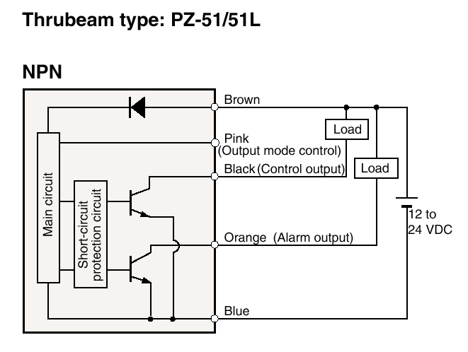
I've already modified the "old" breadboarded potentiometer-based VIWC and bench-tested it to be working. Circuitwise, the only difference between the new more user-friendly VIWC and the former is the replacement of the pot with a momentary contact switch, the addition of a Sonalert buzzer to provide user feedback, and the use of a different MCU--the PIC12F615. The interface with the Innova's wiper module remains unchanged.


I've dumped the 10F222 and chosen a midrange PIC since I'd like to have interrupts to ease my code-writing job and so as to have access to more timers. I always want more timers!

There's really nothing much else to say about the electronics so let's talk about what this improved VIWC does and discuss the firmware.


What the VIWC Does:

Because it's the bedrock on which the intermittent control rests let's first define and discuss the two modes the wiper circuit can be in:
  1. Reset mode -- Entered into by pressing button PB for at least half a second. Upon entering reset mode a short audible alert will sound. In this mode circuit simply records time elapsed since the last wipe. No wipe will be performed until user presses PB again (momentarily or otherwise).
  2. Wipe mode -- Entered into by pressing PB for less than half a second. Upon pressing, a single windshield wipe will be performed and the elapsed time since the last wipe becomes the time interval for all succeeding wipes. The circuit will now automatically sweep the windshield using the recorded time interval until that time PB is pressed again.

Upon power-up a wipe is performed and circuit is put in reset mode. An audible alert (40ms beep followed by 40ms silence followed by a 40ms beep) is issued to inform the driver of this status. No further wipes will be performed until the user presses PB (for less than 0.5s to enter wipe mode or greater than 0.5s to enter reset mode).

When the user presses PB for <0.5s the circuit enters wipe mode. A wipe is immediately performed. The time interval between the last and current wipe is recorded and used as the interval for all succeeding wipes which are automatically performed until that time PB is pressed again.

If the next button press is <0.5s then as before a wipe is immediately performed and the time interval between the last and current wipe is recorded and used as the interval for all succeeding wipes. This implies that momentary button presses (<0.5s) can be used to shorten wipe time intervals but not lengthen them. To do that reset mode is necessary to "teach" the circuit the desired longer time interval.

If the user holds PB down for at least 0.5s the circuit enters reset mode. An audible alert sounds and the circuit will keep recording the time elapsed since the last wipe while waiting for a button press. No further wipes will be performed until PB is pressed.

The following example should make the operation crystal clear.

It's drizzling lightly so the driver switches on the VIWC. Audible alert sounds to inform the driver that reset mode is active. Wiper sweeps the windshield once. After 13 seconds the view through the windshield becomes unduly hindered by the amount of raindrops. The driver presses button PB for a fraction of second. A wipe action is immediately performed. Now every 13 seconds thereafter the windshield is wiped.

Some time later the drizzle weakens, requiring wipe interval to be increased. So the user holds the button down for over half a second. A wipe is performed immediately upon pressing (wipe mode is entered). Half a second after button is pressed the audible alert sounds signalling that reset mode is activated. Some 28 seconds later the driver needs the windshield swept clean. So s/he presses PB momentarily. A wipe is performed and the wipe time interval is set to 28 seconds. The circuit then automatically wipes the windshield every 28 seconds thereafter.

After several minutes the drizzle begins to intensify. After 17 seconds from the last wipe user pushes PB momentarily to clean the windshield. Wiper switches on and time interval is now set to 17 seconds. A couple more minutes pass and the rain intensifies further. 5 seconds after the last wipe the user needs the windshield cleared and so presses button momentarily. Wiper immediately switches on. Circuit will now use a time interval of 5 seconds for succeeding wipes.

In this example the amount of time is explicitly stated only so that circuit operation can be succinctly explained and clearly understood. Needless to say the driver does not count or keep track of the number of seconds from the last wipe before he presses the button.


Firmware Details

All three timers of the 12F615 are used. Nominal timer tick periods given their respective initialized parameters are as follows:

timer0 = 8ms
timer1 = 100ms
timer2 = 50ms

Timer0 tick determines when program execution in main() occurs. Tick of 8ms was chosen for switch debouncing purposes. This is sufficient time to finish functions DebounceSwitch() and ModeCheck().

Timer1 is always on and used to measure elapsed time between wipes. Timer1 interrupt is always enabled.

Timer2 is turned on when a wipe is performed and turned off when wipe is compeleted. It is dedicated to determining how long the wiper motor will be on. Timer2 interrupt is always enabled.

Measurement of wipe time interval: Timer 1 is used to measure wipe time interval. Timer1's 16-bit register and prescaler as well as the 16-bit integer (ELAPSEDTIME) used to record elapsed time are all reset zero whenever wiper is turned on. Therefore, elapsed time (and therefore wipe time interval) is measured from the instant wiper is turned on to the time it is turned on again. The user can set the time interval by pressing the button at two different points in time. However, if measured time between button presses is less than a minimum amount (2 seconds), then firmware will set time interval = 2 seconds

Button is debounced by taking readings every timer0 tick. The instantaneous value is shifted into the LSB of 8-bit register PB.val. The oldest reading is discarded. Switch is deemed not bouncing if the last 8 readings (8 bits) are high or low (PB.val = 0xFF or 0x00). The voltage level of the switch is deemed to be high if all 8 are high and low if all 8 bits are low. When the voltage level changes--high to low or low to high--this is taken as a falling or rising edge.

The reset mode audible alert takes around 120ms to complete and thus temporarily breaks the neat timer0 tick cadence. During this time PB is not read and debounced.

If PB is pressed within 1.5s from the moment wiper was switched on then no wipe action occurs and timer1 and elapsed time counter are not reset. In other words, any and all falling edges detected within that 1.5s period (constant deadtime) are ignored. However, the button hold down time is still monitored and if it exceeds resetmodetime then reset mode is entered.

The various times related to the wiper being turned on are:
Wiper cycle time (measured with stalk switched to INT) = ~1.3s
Wiper on time (determined by constant wipertrigtime) = 1s
PB press dead time (determined by constant deadtime) = 1.5s
Mininum wipe time interval (determined by constant mininterval) = 2s

The relationship between them is wipertrigtime < wiper cycle time < deadtime <= mininterval. The following illustration says it all.

wipertrigtime must of course be < wiper cycle time so that the wiper parks properly. deadtime has to be > wiper cycle time in order that the wiper isn't retriggered before it has parked. And naturally mininterval should be at least equal to deadtime. It doesn't make sense to have it less than deadtime.

Holding down PB for an extended period will merely keep the circuit in reset mode. And the audible alert will keep repeating. It does not reset the elapsed time counter. That only happens if wipe action occurs. And with respect to PB that happens only during a falling edge detect (unless that falling edge occurs within the PB dead time). So the user always knows when elapsed time measurement begins and ends just by noting when the wiper blades move.

/*

Variable Intermittent Wiper Circuit that Learns from User Input
for the Toyota Innova

June 2011
Edwardson Tan

processor = PIC12F615
compiler = mikroC Pro v4.60

*/


#define  buzzer              GPIO.f4             // sonalert buzzer
#define  wiper               GPIO.f5             // 2N7000 switches relay which switches wiper low speed
#define  pb                  GPIO.f2             // momentary contact switch

#define  tris_pb             TRISIO.f2           // used to set pb pin as input
#define  wpu_pb              WPU.f2              // used to enable weak pull up for pb

#define  t0_init_val         256 - 250           // value loaded into TMR0 every time it overflows
#define  t0tick              8                   // timer0 tick time in milliseconds = [(256 - t0_init_val) * prescale / 1MHz] * 1000ms

#define  t1h_init_val        256 - 195           // value loaded into TMR1H every time it rolls over to zero for timer1 to count 0.25sec at a prescale = 1:8 and clock of 4MHz
#define  t1tick              100                 // timer1 tick time in milliseconds = [(256 - t1_init_val) * 256 * prescale / 1MHz] * 1000ms

#define  t2tick              50                  // timer2 tick time in milliseconds = [PR2 * prescale * postscale / 1MHz] * 1000ms

#define  resetmodetime       500/t0tick          // mininum amount of time pb is held down before reset mode is entered. time in terms of timer0 ticks
#define  wipertrigtime       1000/t2tick         // amount of time wiper is turned on. time is in terms of timer2 ticks
#define  deadtime            1500/t1tick         // mininum elapsed time before a button press will trigger a wipe. time is in terms of timer1 ticks
#define  mininterval         2000/t1tick         // mininum time interval between wipes. time is in terms of timer1 ticks

#define  mode                FEN.f0              // 0 = wipe mode,  1 = reset mode
#define  wipe                0
#define  reset               1

#define  rising              1                   // rising edge detected. used by PB.edge
#define  released            1                   // falling edge detected. used by PB.edge
#define  falling             2                   // falling edge detected. used by PB.edge
#define  pressed             2                   // rising edge detected. used by PB.edge
#define  none                0                   // no edge. used by PB.edge

#define  int8                unsigned char
#define  int16               unsigned int
#define  int32               unsigned long

#define  on                  1
#define  off                 0

#define  yes                 1
#define  no                  0

#define  input               1         // for TRISx
#define  output              0         // for TRISx

#define  analog              1         // for ANSELx
#define  digital             0         // for ANSELx

#define  hi                  1         // switch level high
#define  lo                  0         // switch level low

#define  all_bits_hi         0xFF      // for setting an 8-bit register to 255
#define  all_bits_lo         0         // for setting an 8-bit register to 0


// ==================================================================================================================
//       Global Variables
// ==================================================================================================================

struct
{
  val : 8;                             // last eight readings push button. if 0x0 then level is lo, if it is = all_bits_hi then level is hi, any other value means switch is bouncing
  level : 1;                           // level of push button when not bouncing (hi = 1, lo = 0)
  edge : 2;                            // 0 = no edge detect, 1 = rising edge, 2 = falling edge; 3 = Not Used / Undefined for now
}
PB;

int8    PBHELDDOWN;                    // number of timer0 overflows pb has been held down (ie. how long PB.level has been low)
int16   ELAPSEDTIME;                   // elapsed time since the last wipe, in terms of timer1 ticks
int16   WIPEINTERVAL;                  // user selected time interval between wipes, in terms of timer1 ticks
int8    T2COUNTER = 0;                 // stores number of timer2 interrupts that have occured. for use with wiper on time
int8    FEN = 0;                       // Flag and ENable and status bits register
 
// ==================================================================================================================
//       Functions
// ==================================================================================================================

// 1 centisecond = 10 milliseconds = 0.01sec
void DelayCentisec(int8 csec)
{
  int8 i;
  for (i=1; i<=csec; i++)
  {
    Delay_ms(10);
    asm{clrwdt}                        // WDT timeout = 18ms. Therefore it must be cleared here
  }
}

// note: this routine takes over a hundred milliseconds to execute, obviously! it will not finish within the timer0 tick of 8ms
void BeepReset()
{
  buzzer = on;
  DelayCentisec(4);
  buzzer = off;
  DelayCentisec(4);
  buzzer = on;
  DelayCentisec(4);
  buzzer = off;
}

// wiper is turned on
// timer2 is turned on
// timer1 registers and prescaler and 16-bit variable that records elapsed time since last wipe are all reset to zero
// note: wiper will be turned off in the ISR
void Wipe()
{
  wiper = on;
  T2CON.TMR2ON = on;
  TMR1L = 0;
  TMR1H = t1h_init_val;
  ELAPSEDTIME = 0;
}

void InitRegisters()
{
  // I/O pins
  // all are output except for pb, weak pull enabled for pb, all I/Os are digital, clear output pins
  GPIO = 0;
  ANSEL = digital;
  TRISIO = output;
  tris_pb = input;
  wpu_pb = on;

  // timer0 registers
  // given 4MHz clock, prescale = 1:32, TMR0 init val = 6
  // timer0 tick = (256 - 6)(32)(1us) = 8.00ms
  // TMR0 doesn't need to be initialized to any value since the first wipe action will take one second (firmware waits until this is wipe is over) and by then T0IF will be set whatever TMR0 initial value was
  OPTION_REG = 0b100;                  // global weak pull ups on, prescaler assigned to timer0, prescale = 1:32

  // timer1 registers
  // given 4MHz clock, prescale = 1:2, TMR1H init val = 61
  // timer1 tick = (256 - 61)(256)(2)(1us) = 99.84ms
  // upon power up timer1 runs continuously; it is never stopped, but TMR1L and TMR1H are reinitialized upon button press
  T1CON = 0b010001;                    // prescale = 1:2, timer1 source = internal clock, timer1 on
  TMR1L = 0;
  PIE1.TMR1IE = on;

  // timer2 registers
  // given 4MHz clock, prescale = 1:16, postscale = 1:16, PR2 = 195
  // timer2 tick = (195)(16)(16)(1us) = 49.92ms
  // timer2 dedicated to
  T2CON = 0b1111011;                   // postscale = 1:16, timer2 off, prescale = 1:16
  PR2 = 195;                           // when timer2 running TMR2 will increment until it matches PR2 and then TMR2 will be reset
  TMR2 = 0;
  PIE1.TMR2IE = on;

  // initialize to no-button-press condition
  PB.val = all_bits_hi;
  PB.level = hi;
  PB.edge = none;
  
  mode = reset;                        // circuit starts up in reset mode, i.e., wiper will sweep windshield once upon power up and then wait for user to trigger wiper to lock in wipe time interval
  WIPEINTERVAL = mininterval;

  INTCON.GIE = on;
  INTCON.PEIE = on;
}

// The following debounce and edge and level detect routine is performed every timer0 tick
void DebounceSwitch()
{
  // shift all bits to the left
  // if switch reading is hi then PB.val bit0 gets set
  PB.val <<= 1;
  if (pb)
    ++PB.val;

  // if pb has been pressed then start counting how long it is kept pressed
  // a key is said to be pressed when level is lo
  // if level is high then reset counter
  if (!PB.level)
    ++PBHELDDOWN;
  else
    PBHELDDOWN = 0;

  // assume no edge detected
  PB.edge = none;
  
  // if level is lo and all bits of PB.val are now hi then
  // a rising edge has been detected
  // switch is considered just released when rising edge is detected
  // switch level is now hi
  if ((!PB.level) && (PB.val == all_bits_hi))
  {
    PB.level = hi;
    PB.edge = rising;
  }

  // if level is hi and all bits of PB.val are now low then
  // a falling edge has been detected
  // switch is considered just pressed when falling edge is detected
  // switch level is now lo
  if ((PB.level) && (PB.val == 0))
  {
    PB.level = lo;
    PB.edge = falling;
  }
} // void DebounceSwitch()


// This function will check if pb has been pressed
// If pressed then wipe action will be issued and wipe mode is entered
// However, button press--falling edge dected--is ignored if it occurs less than deadtime from the last wipe
// if button is held down > for a time greater than resetmodetime then reset mode is entered.
// note: ELAPSEDTIME is reset to zero in the function Wipe()
void ModeCheck()
{
  if (PB.edge == falling && ELAPSEDTIME >= deadtime)
  {
    WIPEINTERVAL = ELAPSEDTIME;
    if (WIPEINTERVAL < mininterval)
      WIPEINTERVAL = mininterval;
    mode = wipe;
    Wipe();
  }
  else if (PBHELDDOWN >= resetmodetime)
  {
    mode = reset;
    PBHELDDOWN = 0;
    BeepReset();
  }
}

void interrupt()
{
  if (PIR1.TMR1IF)
  {
    TMR1H = t1h_init_val;
    PIR1.TMR1IF = off;
    ++ELAPSEDTIME;
    if ((mode == wipe) && (ELAPSEDTIME >= WIPEINTERVAL))    // if time interval has already been entered by user, then wipe action will automatically be performed after every time interval
      Wipe();
  } // if (PIR1.TMR1IF)
  
  if (PIR1.TMR2IF)
  {
    PIR1.TMR2IF = 0;
    if (++T2COUNTER >= wipertrigtime)
    {
      wiper = off;
      T2CON.TMR2ON = off;
      T2COUNTER = 0;
      TMR2 = 0;
    }
  } // if (PIR1.TMR2IF)
} // void interrupt()


// ==================================================================================================================
//       main
// ==================================================================================================================

void main()
{
  InitRegisters();
  Wipe();
  BeepReset();
  // while(wiper);              // wait till wipe has finished before proceeding, so that any pb press will have no effect
  
  while(1)
  {
    if (INTCON.T0IF)
    {
      asm{clrwdt}
      INTCON.T0IF = off;
      TMR0 = t0_init_val;
      DebounceSwitch();
      ModeCheck();
    } // if (INTCON.T0IF)
  } // while(1)
} // void main()


Testing the VIWC

To see if the circuit and firmware are really working as expected I hooked up the 
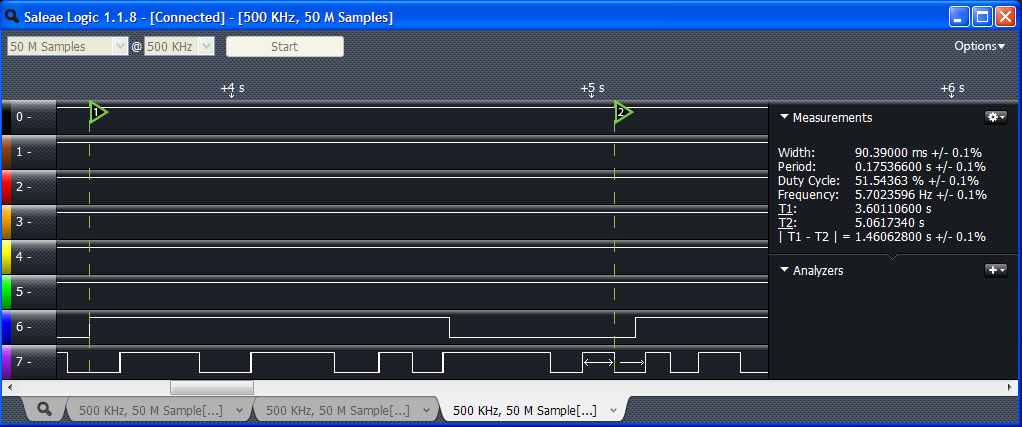
Saleae logic analyzer to the PIC12F615's GP2 pin (PB) and GP5 (Q1 gate). In the text Q1 was driving only an LED not REL2. A really small tactile switch was used for PB. Circuit was powered via PICkit2 set to 5.0V. In all of the screenshots below channel 6 is hooked up to GP5 and channel 7 to GP2.

I wish I could've set the sampling rate to 1MHz and higher but my decade-old computer only has USB1.0 which limits the Saleae to 500kHz. Not infrequently it can't even maintain that and I've experienced the rate going down to 200kHz.

In the first screen capture below the green vertical cursors 1 and 2 have been positioned at the falling edge of GP2 and rising edge of GP5. You can see that |T1 - T2| = 62.6ms. This delay between PB press and wiper switch on is as expected due to the switch debouncing routine which requires all 8 bits of PB.val to be either high or low before a level change is said to have occurred. Those eight bits take eight timer0 ticks. At 8ms, we would expect a nominal 64ms from the actual falling edge of GP2 to the moment wiper is switched on.

Take a look at the amount of time GP5 is high. The pulse width is almost exactly 1 second as we have specified. Note the second falling edge of GP2--PB was pressed again momentarily--causing a wipe action to occur and setting the wipe interval = 4 seconds (read the item labeled "Period")


Zooming in and measuring how long PB was pressed we see that the pulse width is almost 120ms.
 

The shot below shows the wipe interval of succeeding wipes is still 4seconds (3.98s in the instance below). Keep in mind that timer1 tick = 100ms so that's the tolerance value. 


I intentionally waited for the LED to light and then pressed PB rapidly. Remember we specified deadtime = 1.5s so a falling edge on or after an elapsed time of 1.5sec after GP5 goes high should be recognized. Well apparently this did not happen as the shot below shows. Wiper was turned on only after some 1.92s. Is the firmware buggy?


After closer inspection it turns out that I was pressing PB at such a rate that some presses (level low) and nonpresses (level high) were shorter than the required debouncing period of 64ms. Take a look at T1-T2 where cursor 2 is at a falling edge of PB. It's 1.7s. Wiper ought to have been turned on some 64ms after this edge. But then look at the pulse width (rising edge to falling edge). The pulse was high for only 49ms. Because not all bits were high the firmware took this as indicative of switch contacts that are bouncing and thus no valid level change (edge detect) was recognized.


The next button release and button press, on the other hand, met the minimum debouncing requirements: high time was 87ms while low time = 203ms - 87ms = 116ms. Hence wiper was switched on after the valid falling edge was recognized.


Recall that the measured wipe interval was 1.92s. This is less than the minimum of 2s we specified. Thus for the succeeding wipes, firmware set the wipe interval to 2s, with actual period measured to be 1.99s.


The next screenshots are from a different set of data capture. In this first image time between GP2 falling edge and GP5 rising edge is 60ms. The wipe interval is a mere 1.52ms--this violates the minimum and so we should see it changed to 2s in the next wipe (if no button presses occur within that interval).


I moved the cursors to measure the the elapsed time from the moment wiper was turned on to the moment when the falling edge which triggers the wiper occurs. T1-T2 = 1.46s. Doesn't this violate the 1.5s deadtime requirement? No it doesn't. Remember that the debouncing routine needs 64ms to "see" an actual falling edge. So the nominal dead time between wiper turn on and actual (in contrast to firmware determined) falling edge = 1.5s - 64ms = ~1.44s 


As expected in the very next wipe the time interval has been adjusted to conform to the minimum of 2s. Actual measured period = 1.99s.


Here I held down PB while GP5 was still high (LED still on). Pulse width (time PB was held down) = 1.05s. Having pressed PB during the dead time, no wipe occurred. But because PB was pressed for >0.5s, reset mode became active--as can be seen no wipe occurred after 2s (the wipe time interval before the reset). Wiper turns on again only after PB was pressed again.


These last two shots show that elapsed time / wipe interval is measured from the moment wiper is switched on (GP5 rising edge) and not when PB is pressed. As you can see the period is 4.18s in both cases even if PB was pressed (to enter reset mode) almost a second after wiper was turned on.


So there you have it. A more or less full documentation of what for me is an exciting implementation of a VIWC. I'm not rushing to fabricate a PCB for it though. I feel there's a need to have an extended pilot test to get a feel for how well it works and to see if there's anything that needs to modified, tweaked, revised. So I'm stashing the prototype and relays and the whole tangle of wires under the dashboard and installing temporary switches on the lower part of the dash for now. And obviously I'll be doing daily rain dances for the next two weeks.


[June 14 edit: I commented out the line "while(wiper);" in main(). That line is unnecessary]

[June 16 edit: Forgot to mention the maximum wipe time interval possible. Given timer1 tick = 0.1s and ELAPSEDTIME being a 16--bit variable, the maximum time the variable can measure before overflowing back to zero = 65,535 * 0.1s = 6553.5s or ~109 minutes. I'm sure! that's sufficient for lightest of drizzles.]

Sunday, June 12, 2011

Variable intermittent wiper control - Part 4

Variable intermittent wiper control - Part 3

It seems I have a couple more things to say about the circuit, matters that are rather important. So this entry will be about tying up loose ends, and then some.

1. When the VIWC is powered, switching the stalk to any of the settings which turns on the front windshield wiper (INT, LO, HI, momentary wipe) will not perform any operation. This is because the wiper motor needs power via W-VDD and W-PP and the module's electronics needs +12V from W-VDD. The only setting that will work--partly at least--is when the spring-loaded stalk is pulled toward the driver. This is the front mist + wiper setting. When the stalk is pulled, the front mist motor will operate and spray water, but the wiper will be nonoperational.

On the other hand, the rear wiper and rear mist are fully functional even with VIWC on. The rotary switch (knob) on the stalk that controls these functions operates normally. This is of course desirable. We'd want to be able to operate the rear wiper and washer regardless of whether the VIWC is on or off.


2. If we want longer time intervals than the 32 seconds we can derive a 6-bit ADC value instead of a 5-bit number. That would give us a maximum of 64 seconds given our algorithm.

We can also vary the step function, i.e., the increment. For instance we can convert the ADC value from 8 to 5 bits and then add 2:

return ((ADRES >> 3) + 2); 

The range of time intervals will then be 2, 4 ,6 ... 64 seconds.

For fractional values, say increments of 1.5 seconds we can do the following:

TIME = (ADC())*20 + 10; 

10 timer ticks = half a second, so the above code will add 0.5sec to the increment value.


3. I used the Saleae Logic to measure the wipe time interval for a few potentiometer settings. Images show below 1, 16, and 32 second intervals. Look at the value for the item marked"Width" for the actual time intervals for the particular chip I used. Probe was connected to 10F222's GP2 pin.


4. Just as I finished writing Part 3 I stumbled upon a forum discussing a most creative and elegant type of variable intermittent wiper. The circuit learns how long the time interval between wipes by monitoring when the user flips a couple of switches.
This wiper delay timer "learns" the wiper interval in the following way: It starts drizzling, so you flick the wipers once. It keeps drizzling so, when the screen is in need of another wipe, you flick it onto intermittent. The wiper delay timer sets itself to the time interval between your initial "flick" of the wipers and when you switched it to intermittent, and carries on using that interval thereafter.
This is such a great and simple idea. And it's more user-friendly than continually tweaking a pot (while driving!) to get the timing right. I had one of those eye-rolling "Why didn't I think of that" moment.

After mulling over the switch requirements, the light bulb flashed, and I figured that for our version of this type of control one momentary contact button would suffice. By holding holding the button for about a second we can inform the MCU that we want to enter time interval record mode, i.e., the circuit will wait for us to press the button again (for just a fraction of second) to lock in the time interval we desire. Thereafter the circuit will use that time period to sweep the windshield. Thereafter should we press the button again for less than second the MCU will shorten the wipe interval time accordingly. Pressing the button for <1sec can't lengthen the time interval, only shorten it. Thus we need to enter record mode which can be done so at anytime by, as before, holding down the key for at least a second.

Looks like the potentiometer-based VIWC has already been obsoleted and shelved even before I've designed a board for it. Which is just as well since I now don't have to expend so many hours on PCB design and fabrication and assembly of a circuit that I probably won't be installing anyway. 


In Part 5 I will have a full discussion of this new type of VIWC. Schematic and firmware will be provided and discussed.

Friday, June 10, 2011

Variable intermittent wiper control - Part 3

Variable intermittent wiper control - Part 2

Rather than use a 555 for the variable intermittent wiper circuit (VIWC) as we saw in Part 1 I employed a microcontroller instead for the Innova. An MCU's timing accuracy is far better than the 555 and is far more powerful and flexible and requires less discrete components.

I chose a baseline PIC with analog to digital converter (ADC) instead of a midrange PIC because I need only two pins and both Flash and RAM requirements are minimal. What I have on hand right now is the PIC10F222, but the 10F220 just might suffice depending on the optimization level available on the compiler--the Hi -Tech C freebie version I use throws up obscenely long codes and probably gobbles up RAM as well.

Given the wiper module's electronics it is necessary to electrically disconnect it from the VIWC to prevent any conflicts and possible shorts. Through tests I've determined that the module's electronics is powered via W-VDD. So disconnecting the circuit from this net will prevent it from being powered up. However, we will be using W-PP and that goes right into the board. W-PP carries a +12V which could possibly wreak havoc on the circuitry particularly with W-VDD cut off. With the wiper stalk switch at OFF and INT, W-PP is connected to W-LO. This is actually fine but no harm in breaking this connection while the VIWC is powered up. Tests thus far show that W-LO isn't connected to the board or relay. So we don't have to sever this connection to the wiper module. We'll just need to tap into it to trigger--briefly turn on--the wiper motor. Here's a diagram of the wires leading to the connectors that we'd need to break. Actually only one connector needs to be modified.

Take note of the new wire labels. Those are used in the following schematic. Note that all switches and relay contacts are shown in their normal position--with the circuit powered down.


In the initial design I opted to use a DPDT switch rather than the DPDT relay. I decided on the relay and SPST switch design because I would be able to use a smaller switch on the dashboard and would have to bring only two wires to it.

REL1 is a Telemecanique RXM2AB2JD  12-volt relay with 12A DPDT contacts and a green LED indicator lamp. REL2 is a 12-volt relay with 10A SPDT contacts.

When S-POW is closed REL1 is energized. Power to wiper module is cut off while the VIWC is powered up. Simultaneously, WW-PP is disconnected from W-PP and connected instead to REL2's NC contact, thus making sure that when REL2 is de-energized the wiper motor will automatically bring the wiper blades back to their parking position.

You will notice I have not used W-GND but connected the circuit directly to chassis ground. Tests show both are the same net even when ignition is off. I want to cut and cut into as few of the car's wires as possible.

For the pot I used a cheap low quality one. Trying to get a particular time interval with it can become vexing. I'm still trying to find a better pot that has a much more even resistance across its entire range. Another option is to use a pot with a switch thus integrating S-POW with R1 in one package.

A 78L05 100-mA voltage regulator provides +5V to the MCU. Filter cap is 100uF.


The microcontroller is run at 4MHz. Watchdog timer is enabled. The prescaler is assigned to timer0 so WDT will time out in 18ms (nominal value as per datasheet). In the firmware WDT is cleared during the polling of TMR0.

With the single 8-bit timer I wanted to get the highest possible tick. At 4Mhz--which translates to a million instructions/sec--that would be 65.536ms with TMR0 = 0 and a prescale of 1:256. But that's not a good tick value. 50ms is easier and more sensible to work with. To obtain that, prescale is set to 1:256 and TMR0 reinitialized to 0x3D (decimal 61) every time it rolls over to zero. Given those values TMR0 will overflow every (256 - 61)(256)(1us) = 49.92ms.

Remember baseline PICs don't have interrupts. We have to poll the timer to determine when it's overflowed. But for some reason using the conditional "while(TMR0 != 0)" doesn't work. Using any value other than zero, however, works. So in the firmware below I have "while(TMR0 != 0xFF)" instead. With that conditional perhaps I should initialize TMR0 to 0x3C instead.

What I wanted was for the time interval between wipes to be increments of 1 second, that is, as the user turns the potentiometer the interval would get longer/shorter but it would jump from 1 second to 2 to 3 and so on, and not fractions thereof. As for maximum interval, I initially specified 60sec but then I settled on 30. Minimum interval would be 1sec.

Note that time interval is defined as the time between de-energization of the REL2 and its re-energization.

In order to realize the above specs, it occured to me there's a simple and elegant way of doing so. The ADC onboard the 10F222 has an 8-bit resolution. That's 256 values, from 0 to 255. Well what we can do is to degrade the resolution to less than 8 bits. That's easily done by right shifting the ADC value (the number the ADC spits out after the conversion). Shift it right twice and we have a 6-bit number--from 0 to 63. Or shift thrice and we a 5-bit value--0 to 31. We can then take those numbers as the time interval (in seconds). But since we specified a minimum of 1 second, we should add 1 to the 5-bit ADC value giving us a range of 1 to 32. Now keep in mind this is the number of seconds. Our timer tick, however, is ~50ms. To get the time interval in terms of ticks we have to multiply the ADC value by 1sec/0.05sec = 20. Therefore, to count 32 seconds, we need to wait for 32(20) = 640 ticks.

The potentiometer is read by the ADC every timer tick. The time interval setting is therefore updated 20 times a second, except when a wipe action is being executed--the ADC is not reading the pot during that time.

The firmware is such that, every timer tick, it compares the latest time interval chosen by user and the amount of time elapsed since the last wipe. If time elapsed already exceeds the latest time interval setting, then a wipe is immediately performed and the 16-bit counter monitoring the amount of time elapsed is reset to zero.

For example if the pot was previously set to a time interval of say 25 sec, and 15 seconds has already elapsed, and the user has just turned the pot down to 12sec, the firmware will immediately issue a wipe action and reset the time elapsed counter. (In reality, with a read rate of 20x a second--somewhat faster than the driver can turn the pot--firmware will see the pot setting crossing the 15sec mark and issue a wipe action at that point). On the other hand, if the user had turned up the pot instead, to say 30sec., then the firmware will count all the way to 30sec before the next wipe.

When powered up an initial wipe is made. Thereafter, when the succeeding wipes will occur will depend on the pot setting. The length of time I've chosen for the wiper to be triggered (turned on briefly) is one second (20 timer ticks). As mentioned in Part 2 the time for the wiper to go from parking position and back was measured to be ~1.3sec. Trigger time must be less than this. A trigger time of around half a second would probably be sufficient. Keep in mind, however, that time interval between wipes is affected by wiper trigger time.

And here's the final firmware to drive the micrcontroller. Compiler used is the Hi -Tech C Lite v9.80. As I mentioned a few days ago the 10F222 include file of v9.81 doesn't define TRIS and so will fail to compile the following.

/*

Variable intermittent wiper control for the Toyota Innova, 2008, E-variant
June 2011

Processor = PIC 10F222 
Compiler = Hi Tech C v.9.80

Description: User adjusts a potentiometer to desired interval between wipes.

*/


#include <htc.h>
#include <et_include.h>

__CONFIG (OSC_4MHZ & MCPUDIS & WDTEN & UNPROTECT & MCLRDIS);        // for Hi-Tech C v9.80
// __CONFIG (IOSCFS_4MHZ & MCPU_OFF & WDT_OFF & CP_OFF & MCLRE_OFF); // for Hi-Tech C v9.81

#define   wiper              GP2       // switches 2N7000 MOSFET transistor which then switches relay which switches wiper
#define   wipertrigtime      20        // amount of time to power up wiper. time is in terms of number of timer0 overflows
#define   t0_init            61        // initial value of timer0. with prescaler = 1:256, overflow occurs every ~50ms 
// #define  _XTAL_FREQ       4000000 


// potentiometer setting is converted to 5-bit digital value
// 10F222 ADC has 8bit resolution, therefore ADC value is right shifted three places
// After right shifting, add 1 so that with ADC value of zero (potentiometer at zero ohms) the minimum time interval is 1sec.
// Since max ADC value for 5-bit is 31, max time interval = 31 + 1 = 32sec
int8 ADC()          
{
  GODONE = 1;                          // start ADC conversion
  while(GODONE);                       // wait till GODONE bit has been cleared, signifying completion of conversion 
  return ((ADRES >> 3) + 1);     // degrade to 5 bits, and force min time interval = 1
}


// wiper lo speed is triggered (switched on) for a brief moment, determined by constant "wipertrigtime" 
// after triggering, parking system on wiper motor will take over powering the motor until it reaches parking position 
// when wiper reaches parking position, motor stops automatically 
// NOTE: WDT must be cleared within 18ms (no prescaler assigned to it)
void WIPE()
{
  int8 i;
  wiper = on;
  for (i=0; i<wipertrigtime; i++)
  {
    TMR0 = t0_init;
    while(TMR0 != 0xFF)      // for yet unknown reason conditional doesn't work with "TMR0 != 0x0"
      CLRWDT();
  }
  wiper = off;  
}


// NOTE: WDT must be cleared within 18ms (no prescaler is assigned to it)
void main()
{
  static int16 TIME = 40;    // number of timer0 overflows (every 50ms) between wiper sweeps. initialize to minimum time interval betwen wipes (2sec. which is equivalent to 40 timer0 overflows) 
  static int16 COUNTER = 0;  // stores the number of times timer0 has overflowed

  TRIS = 0b1;                // pot is connected to AN0/GP0
  OPTION = 0b11000111;       // wake up pin change disabled, pull ups disabled, timer0 uses internal clock, timer0 prescale = 1:256 
  WIPE();                    // have wiper sweep windshield once upon power up
  TMR0 = t0_init;
  ADCON0 = 0b10000001;       // GP0/AN0 is analog, GP1 is digital, channel 0 selected, ADC on
  
  while(1)
  {
    while(TMR0 != 0xFF)      // poll TMR0 because there is no timer0 interrupt flag. for yet unknown reason conditional doesn't work with "TMR0 != 0x0"  
      CLRWDT();              // WDT must be cleared within 18ms (no prescaler assigned to it)

    if (COUNTER++ >= TIME)
    {
      WIPE();
      COUNTER = 0;           
    }
    TMR0 = t0_init;
    
    TIME = (ADC())*20;       // Each value of the 5-bit ADC reading is equivalent to number of seconds. 
                             // This is then multiplied by 20 since timer0 overflows every 50ms and 1sec/0.050sec = 20
                             // if new TIME < previous TIME and current COUNTER value exceeds new TIME then a wipe will occur right after the next TMR0 overflow
                             // if new TIME > previous TIME then whatever COUNTER is, the next wipe will occur at a later time.   

  } // while(1) 
} // void main()


I field tested the circuit to check if everything works. It does! Here are a couple of pics of that test process. The breadboard is in the translucent plastic box while the relays are mounted on a DIN rail. REL1 and REL2 are both Telemecanique RXM2AB2JD relays. In the PCB version I will be using a small PCB mounted relay for REL2.


There's another shot of this setup in which something very interesting inadvertently appeared.


June 12 edit: A Part 4 just appeared. And because of new developments so will a Part 5.

Wednesday, June 8, 2011

Variable intermittent wiper control - Part 2

Variable intermittent wiper control - Part 1

Before delving into the electrical characteristics of the Innova's wiper system, let me just provide the wipe time. Using a stopwatch the time for the wiper in intermittent mode to make one complete sweep--wiper goes from park position, sweeps the windshield and back to parking--is approximately 1.3sec.


Here again is a shot of the header pins into which the connectors plug.


After testing the wiper switch module here are the pin assignments I came up with:


Testing included using the resistance/continuity mode of a multimeter to check which pins are electrically connected (practically zero ohms) while trying the various switch settings. Testing also involved plugging the connectors into the module--only partially so I can have access to the headers--turning the ignition key until power is supplied to the wiper circuit and probing the headers with the DMM and trying out the different switch settings on the stalk. 

The following summarizes the cold test using the ohmmeter. The presence of links (lines) between pins means those pins are electrically connected at the indicated switch setting.


Below are results of the hot test. All voltage values are with reference to chassis ground. The voltage on some pins jump from one value to another or span a range. This is indicated by the nomenclature "x - y". So "0 - 12V" might mean that voltage toggles between these values or that it smoothly but very quickly rises to 12 or declines to 0. Using a DMM did not allow me to determine whether the readings I was getting were indicative of discontinuous or continuous values.


I also checked the PCB disconnected from the connectors and using an ohmeter had the following results.


The yellow box denotes the location of relay on the other side of the board. Hence the solder points within that outline will be the pins on the relay. The solder joint marked "COIL" is inferred from the fact that there is no other pin for the relay coil. Moreover resistance reading from VDD to COIL is 240 ohms--that's within the ballpark for a 12VDC coil.

What is perplexing to me is that there are two relay pins to which W-PP is connected. Why?! This finding has really been very disconcerting. I would've thought that one of the relay contacts would be hooked up to W-LO. Interestingly, if you look at the W-PP track on the left side you'll see that it leads to the top portion of the board to a solder joint. So W-PP is connected to some other component. The mystery deepens.


With the module disconnected and the ignition key turned to supply power to the wiper (with the engine off), I used a DMM set to current measurement to act as a jumper and to measure peak current as well. Here are the results.

Using DMM probes as jumpers between Net 1 and 2 with a Fluke 87V DMM set to measure current, Min-Max mode on
Net 1 Net 2 Result of connecting jumper Maximum Measured Current (amperes) (see footnote)
W-VDD W-LO front wiper low speed on continuously but stops as soon as jumper removed--wiper does not park automatically 3.1 to 4.0A
W-PP W-LO with wiper initially NOT at parking position, the wiper will move to parking position and then stop; keeping jumper connected does not result in any further action 3.7 to 6.2A
W-VDD W-HI front wiper high speed on continuously but stops as soon as jumper removed--wiper does not park automatically 8.9 to 9.2A
W-RW W-GND rear wiper turns on continuously and parks automatically when jumper removed 1.4 to 1.7A
W-RM W-GND rear mist on as long as jumper connected 2.0 to 2.6A
W-FM W-GND front mist on (wiper does not turn on) as long as jumper connected 2.2 to 2.5A

Note: Current measurements were made several times. Only MAX values as measured by the 87V were recorded. The range of values per item above are the lowest and highest MAX values.


Given all the above data I have drawn up a provisional schematic diagram. However, it almost certainly is incomplete and contains errors so I won't put it up lest some reader relies upon it as gospel truth.

What can be inferred with high confidence at this time are the following :
  • Switching the stalk to LO disconnects W-PP from W-LO and connects W-VDD and W-LO, feeding +12V to the wiper motor's low speed circuit. 
  • When the stalk is returned to OFF, W-PP is once again connected to W-LO thus automatically parking the wiper.
  • When stalk is switched to INT W-PP remains connected to W-LO. The electronic circuit comes into play and switches the on-board relay for about a second every couple of seconds. Judging from the clicks of the relay it is being turned off right at the moment of wiper parking (which makes me wonder yet again how W-PP is being used by the PCB).
  • When the stalk is switched to HI, W-PP is not connected to W-LO. W-VDD is connected to W-HI thus supplying +12V to the wiper motor's high speed circuit.
  • When stalk is pushed all the way up (switched to MIST--this is a mislabel on Toyota's part since it doesn't turn on the spray) the spring-loaded switch is engaged and W-PP is disconnected from W-LO while W-VDD is connected to W-LO thus supplying +12V to the wiper motor's low speed circuit. Releasing the stalk returns it to OFF position and thus W-PP gets connected to W-LO and the wiper parks automatically.
  • From the OFF position, when stalk knob is turned counterclockwise (i.e., turning it toward the driver) to the rear windshield spray icon, W-RM is grounded (connected to W-GND) turning on rear mist motor.
  • From the off position, when stalk knob is turned clockwise (i.e., turned toward the dashboard) one notch to ON, W-RW is grounded (connected to W-GND) switching on the rear wiper motor.
  • With the rear wiper on, when the stalk knob is turned clockwise to the second rear windshield spray icon, both W-RW and W-RM are connected to W-GND, hence both rear wiper and rear mist are switched on. This is a spring-loaded setting and releasing the knob will return the knob to the rear-wiper-on position and the rear mist motor will be switched off.  
  • When spring-loaded stalk is pulled toward the driver W-FM is connected to ground via W-GND thus turning on the front mist motor. Because W-FM is connected to the PCB (see labeled PCB pic above), the circuit board most probably senses the level change from 12 to 0 volts. After a brief delay (~0.5sec) from the start of the mist the relay is turned on hence switching on the low speed motor circuit. The relay is kept on for several seconds so that the wiper makes at least three wipes. 


In Part 3 I'll discuss a microcontroller-based variable intermittent wiper circuit for the Innova and provide a full listing of the firmware.