Friday, October 21, 2011

Cascading (snowfall) LED lights

I first saw these kinds of lights some two years ago and back then didn't know what they were called so I dubbed them raindrop lights. Check out the following vids for a couple of variations of cascading lights: http://youtu.be/FK-wlvhhtXk and http://youtu.be/qR4DLUNAbAo. The first vid has a close-up of the unit, showing--to my surprise--DIP ICs and 1/4 Watt resistors. The LEDs these units use are of the type which can be seen from practically any direction.

Just as a challenge I wanted to emulate the effect using ordinary white LEDs and a microcontroller. After some trial and error I got the firmware working. I'm sure it could be improved upon and different variations could be implemented. For instance as in the second vid above, the cascade could be made without PWM, leaving fading for the very last LED.

So here's a vid of the breadboarded circuit. The firmware that drives it follows. If anyone will be so kind enough to donate a real video cam the pic quality can be greatly enhanced  :-)


/*

Cascading (Snowfall or Meteor) LED Lights
October 16 2011

processor = PIC16F1827
compiler = mikroC v5.0.0

(configuration settings -- copied from mikroC's "Edit Project" window)
CONFIG1   :$8007 : 0x0F84
CONFIG2   :$8008 : 0x1613

*/


// if using different PORT pins just change the assignments below
// the firmware does not need to be edited
#define  led1                LATA.f1             // led1 is the first LED to be lit (topmost LED of the cascade)
#define  led2                LATA.f0
#define  led3                LATA.f7
#define  led4                LATA.f6
#define  led5                LATB.f7
#define  led6                LATB.f6
#define  led7                LATB.f5
#define  led8                LATB.f4
#define  led9                LATB.f3
#define  led10               LATB.f2
#define  led11               LATB.f1
#define  led12               LATB.f0
#define  led13               LATA.f4
#define  led14               LATA.f3
#define  led15               LATA.f2             // led15 is the last LED to be lit (bottom LED of the cascade)
#define  lastled             led15               // this is used in the Twinkle() function

// following used for twinkle effect
#define  fadeintime          2                   // number of PWM periods for each pulse width during fade in from min to max brightness
#define  fadeouttime         7                   // number of PWM periods for each pulse width during fade out from max to min brightness
#define  twinkle_delay       1                   // deciseconds between the end of the cascade and beginning of twinkle effect
                                                 // during this time led15 is off

#define  cascade_delay       20                  // deciseconds between cascades. during this time all LEDs are off
                                                 // time begins after Twinkle()

#define  t0_ini              256-128             // TMR0 initialize value every time it overflows
#define  t1h_ini             256-98              // TMR1H initialize value every time it overflows
#define  cascadetime         10                  // number of cycles (PWM periods) per stage
#define  maxstage            22                  // maximum number of stages
                                                 // a stage is when a set of LEDs are lit
                                                 // each successive stage moves the cascade by one LED

#define  int1                bit
#define  int8                unsigned char
#define  int16               unsigned int
#define  int32               unsigned long

#define  on                  1
#define  off                 0

// ==================================================================================================================

void IniReg()
{
  OSCCON = 0b1110000;        // 8MHz
  TRISA = 0;
  TRISB = 0;
  ANSELA = 0;
  ANSELB = 0;
  LATA = 0;
  LATB = 0;
  T1CON = 0b110000;          // prescale = 1:8, timer1 off
                             // given 8MHz, TMR1H = 98 counts, prescale = 1:8, timer1 tick = ~100ms
} // void IniReg()


// During the start of each PWM period the LEDs that will be "PWMed" for that stage are turned on.
void IniLEDs(int8 STAGE)
{
  switch (STAGE)
  {
    case 1:
      led1 = on;
      break;

    case 2:
      led1 = on;
      led2 = on;
      break;

    case 3:
      led1 = on;
      led2 = on;
      led3 = on;
      break;

    case 4:
      led1 = on;
      led2 = on;
      led3 = on;
      led4 = on;
      break;

    case 5:
      led1 = on;
      led2 = on;
      led3 = on;
      led4 = on;
      led5 = on;
      break;

    case 6:
      led1 = on;
      led2 = on;
      led3 = on;
      led4 = on;
      led5 = on;
      led6 = on;
      break;

    case 7:
      led1 = on;
      led2 = on;
      led3 = on;
      led4 = on;
      led5 = on;
      led6 = on;
      led7 = on;
      break;

    case 8:
      led1 = on;
      led2 = on;
      led3 = on;
      led4 = on;
      led5 = on;
      led6 = on;
      led7 = on;
      led8 = on;
      break;

    case 9:
      led2 = on;
      led3 = on;
      led4 = on;
      led5 = on;
      led6 = on;
      led7 = on;
      led8 = on;
      led9 = on;
      break;

    case 10:
      led3 = on;
      led4 = on;
      led5 = on;
      led6 = on;
      led7 = on;
      led8 = on;
      led9 = on;
      led10 = on;
      break;

    case 11:
      led4 = on;
      led5 = on;
      led6 = on;
      led7 = on;
      led8 = on;
      led9 = on;
      led10 = on;
      led11 = on;
      break;

    case 12:
      led5 = on;
      led6 = on;
      led7 = on;
      led8 = on;
      led9 = on;
      led10 = on;
      led11 = on;
      led12 = on;
      break;

    case 13:
      led6 = on;
      led7 = on;
      led8 = on;
      led9 = on;
      led10 = on;
      led11 = on;
      led12 = on;
      led13 = on;
      break;

    case 14:
      led7 = on;
      led8 = on;
      led9 = on;
      led10 = on;
      led11 = on;
      led12 = on;
      led13 = on;
      led14 = on;
      break;

    case 15:
      led8 = on;
      led9 = on;
      led10 = on;
      led11 = on;
      led12 = on;
      led13 = on;
      led14 = on;
      led15 = on;
      break;

    case 16:
      led9 = on;
      led10 = on;
      led11 = on;
      led12 = on;
      led13 = on;
      led14 = on;
      led15 = on;
      break;

    case 17:
      led10 = on;
      led11 = on;
      led12 = on;
      led13 = on;
      led14 = on;
      led15 = on;
      break;

    case 18:
      led11 = on;
      led12 = on;
      led13 = on;
      led14 = on;
      led15 = on;
      break;

    case 19:
      led12 = on;
      led13 = on;
      led14 = on;
      led15 = on;
      break;

    case 20:
      led13 = on;
      led14 = on;
      led15 = on;
      break;

    case 21:
      led14 = on;
      led15 = on;
      break;

    case 22:
      led15 = on;
      break;

    default:
      break;
  } // switch (STAGE)
} //void IniLEDs()


// Within the PWM period, LEDs are turned off when their particular pulse width has been reached.
void SwitchLEDs(int8 STAGE, int8 PWEXP)
{
  switch (PWEXP)
  {
    case 0:
      switch (STAGE)
      {
        case 8:
          led1 = off;
          break;

        case 9:
          led2 = off;
          break;

        case 10:
          led3 = off;
          break;

        case 11:
          led4 = off;
          break;

        case 12:
          led5 = off;
          break;

        case 13:
          led6 = off;
          break;

        case 14:
          led7 = off;
          break;

        case 15:
          led8 = off;
          break;

        case 16:
          led9 = off;
          break;

        case 17:
          led10 = off;
          break;

        case 18:
          led11 = off;
          break;

        case 19:
          led12 = off;
          break;

        case 20:
          led13 = off;
          break;

        case 21:
          led14 = off;
          break;

        case 22:
          led15 = off;
          break;

        default:
          break;
      }
      break;

    case 1:
      switch (STAGE)
      {
        case 7:
          led1 = off;
          break;

        case 8:
          led2 = off;
          break;

        case 9:
          led3 = off;
          break;

        case 10:
          led4 = off;
          break;

        case 11:
          led5 = off;
          break;

        case 12:
          led6 = off;
          break;

        case 13:
          led7 = off;
          break;

        case 14:
          led8 = off;
          break;

        case 15:
          led9 = off;
          break;

        case 16:
          led10 = off;
          break;

        case 17:
          led11 = off;
          break;

        case 18:
          led12 = off;
          break;

        case 19:
          led13 = off;
          break;

        case 20:
          led14 = off;
          break;

        case 21:
          led15 = off;
          break;

        default:
          break;
      }
      break;

    case 2:
      switch (STAGE)
      {
        case 6:
          led1 = off;
          break;

        case 7:
          led2 = off;
          break;

        case 8:
          led3 = off;
          break;

        case 9:
          led4 = off;
          break;

        case 10:
          led5 = off;
          break;

        case 11:
          led6 = off;
          break;

        case 12:
          led7 = off;
          break;

        case 13:
          led8 = off;
          break;

        case 14:
          led9 = off;
          break;

        case 15:
          led10 = off;
          break;

        case 16:
          led11 = off;
          break;

        case 17:
          led12 = off;
          break;

        case 18:
          led13 = off;
          break;

        case 19:
          led14 = off;
          break;

        case 20:
          led15 = off;
          break;

        default:
          break;
      }
      break;

    case 3:
      switch (STAGE)
      {
        case 5:
          led1 = off;
          break;

        case 6:
          led2 = off;
          break;

        case 7:
          led3 = off;
          break;

        case 8:
          led4 = off;
          break;

        case 9:
          led5 = off;
          break;

        case 10:
          led6 = off;
          break;

        case 11:
          led7 = off;
          break;

        case 12:
          led8 = off;
          break;

        case 13:
          led9 = off;
          break;

        case 14:
          led10 = off;
          break;

        case 15:
          led11 = off;
          break;

        case 16:
          led12 = off;
          break;

        case 17:
          led13 = off;
          break;

        case 18:
          led14 = off;
          break;

        case 19:
          led15 = off;
          break;

        default:
          break;
      }
      break;

    case 4:
      switch (STAGE)
      {
        case 4:
          led1 = off;
          break;

        case 5:
          led2 = off;
          break;

        case 6:
          led3 = off;
          break;

        case 7:
          led4 = off;
          break;

        case 8:
          led5 = off;
          break;

        case 9:
          led6 = off;
          break;

        case 10:
          led7 = off;
          break;

        case 11:
          led8 = off;
          break;

        case 12:
          led9 = off;
          break;

        case 13:
          led10 = off;
          break;

        case 14:
          led11 = off;
          break;

        case 15:
          led12 = off;
          break;

        case 16:
          led13 = off;
          break;

        case 17:
          led14 = off;
          break;

        case 18:
          led15 = off;
          break;

        default:
          break;
      }
      break;

    case 5:
      switch (STAGE)
      {
        case 3:
          led1 = off;
          break;

        case 4:
          led2 = off;
          break;

        case 5:
          led3 = off;
          break;

        case 6:
          led4 = off;
          break;

        case 7:
          led5 = off;
          break;

        case 8:
          led6 = off;
          break;

        case 9:
          led7 = off;
          break;

        case 10:
          led8 = off;
          break;

        case 11:
          led9 = off;
          break;

        case 12:
          led10 = off;
          break;

        case 13:
          led11 = off;
          break;

        case 14:
          led12 = off;
          break;

        case 15:
          led13 = off;
          break;

        case 16:
          led14 = off;
          break;

        case 17:
          led15 = off;
          break;

        default:
          break;
      }
      break;

    case 6:
      switch (STAGE)
      {
        case 2:
          led1 = off;
          break;

        case 3:
          led2 = off;
          break;

        case 4:
          led3 = off;
          break;

        case 5:
          led4 = off;
          break;

        case 6:
          led5 = off;
          break;

        case 7:
          led6 = off;
          break;

        case 8:
          led7 = off;
          break;

        case 9:
          led8 = off;
          break;

        case 10:
          led9 = off;
          break;

        case 11:
          led10 = off;
          break;

        case 12:
          led11 = off;
          break;

        case 13:
          led12 = off;
          break;

        case 14:
          led13 = off;
          break;

        case 15:
          led14 = off;
          break;

        case 16:
          led15 = off;
          break;

        default:
          break;
      }
      break;

    // for PWEXP = 7, no led need be switched off since it's duty cycle will be gradually decreased anyway in the next STAGE
    // therefore there's no need for a separate case statement. 
    // The default option below will automatically "catch" the case when PWEXP = 7

    default:
      break;
  } // switch (PULSEWIDTH)
} // void SwitchLEDs()


/*
The particular LEDs to be lit and their pulse width depends on the current STAGE. 
At the start of each PWM period all LEDs for the particular stage are turned on.
Then one by one, beginning with the LED that has the least pulse width, they're turned off. 
After the second TMR0 overflow, the prescale value of timer0 is changed every TMR0 overflow as shown in the table below. 
Every time TMR0 overflows it is re-initialized with t0_ini (128decimal).
The total time elapsed is the pulse width of the LEDs. 
The change in PW between the LEDs is exponential. 
The lead LED has a duty cycle of 100%.

PWN period = 8.192ms 
Fosc = 8Mhz
t0 tick = (TMR0 count)*(prescale)/(Fosc/4)

t0_ini  TMR0 count   prescale   t0 tick (us)  total time elapsed (us) 
128        128           1           64               64 
128        128           1           64              128 
128        128           2          128              256 
128        128           4          256              512 
128        128           8          512             1024 
128        128          16         1024             2048 
128        128          32         2048             4096 
128        128          64         4096             8192 
*/
void Cascade()
{
  // OPTREG[] lookup table contains values to be successively loaded into OPTION register during one PWM period
  // timer0 prescale values are {1,1,2,4,8,16,32,64}
  // to obtain timer0 prescale value = 1, prescaler is NOT assigned to timer0
  // timer0 initial value is kept constant at 128decimal
  const int8 OPTREG[] = {0b1000, 0b1000, 0b0, 0b1, 0b10, 0b11, 0b100, 0b101};

  int8 STAGE;                  // at which stage the cascade is currently
  int8 PWEXP;                  // exponent (with base = 2) of the pulse width
  int8 TOTALTIME;              // records number of PWM periods

  PWEXP = 0;
  for (STAGE = 1; STAGE <= maxstage; STAGE++)
  {
    TOTALTIME = 0;
    while (TOTALTIME <= cascadetime)
    {
      if (!PWEXP)                                // initialize (turn on) LEDs only when it's the start of a PWM period
        IniLEDs(STAGE);
      OPTION_REG = OPTREG[PWEXP];
      TMR0 = t0_ini;
      INTCON.T0IF = 0;
      while (!INTCON.T0IF) ;
      SwitchLEDs(STAGE, PWEXP);                   // turn off the LED
      if (++PWEXP > 7)
      {
        PWEXP = 0;
        TOTALTIME++;
      }
    } // while (TOTALTIME <= cascadetime)
  } // for (STAGE=1; STAGE<= maxstage; STAGE++)
} // void Cascade()


// PWM routine for the twinkle effect
void Dim(int8 EXP, int8 FADETIME)
{
  // pulse width (output high = led on) in terms of the value of TMR0, given a fixed timer0 period of 8.192ms
  const int8 PW[] = {1, 2, 4, 8, 16, 32, 64, 128, 255};

  int8 TOTALTIME = 0;
  int8 PULSEWIDTH;

  TMR0 = 0;
  INTCON.T0IF = 0;
  PULSEWIDTH = PW[EXP];

  while (TOTALTIME++ <= FADETIME)
  {
    lastled = on;
    while (TMR0 < PULSEWIDTH);
    lastled = off;
    while (!INTCON.T0IF);
    INTCON.T0IF = 0;
  }
}

// twinkle effect where fade in time and fade out time are or can be different
void Twinkle()
{
  int8 i;
  
  OPTION_REG = 0b10000101;             // timer0 prescale = 1:64
  for (i = 0; i <= 8; i++)
    Dim(i, fadeintime);
  for (i = 7; i > 0; i--)
    Dim(i, fadeouttime);
  lastled = off;
} // void Twinkle()


// delay in deciseconds
// as an alternative timer0 can be used instead of timer1 if, say, using an MCU with only one timer
void DelayDsec(int8 dsec)
{
  int8 i;

  TMR1L = 0;
  T1CON.TMR1ON = 1;
  for (i = 0; i < dsec; i++)
  {
    TMR1H = t1h_ini;
    PIR1.TMR1IF = 0;
    while (!PIR1.TMR1IF);
  }
  T1CON.TMR1ON = 0;
} // void DeadTime()


void main()
{
  IniReg();
  while(1)
  {
    Cascade();
    DelayDsec(twinkle_delay);
    Twinkle();
    DelayDsec(cascade_delay);
  }
} // void main()


----

November 23 2011 Addendum

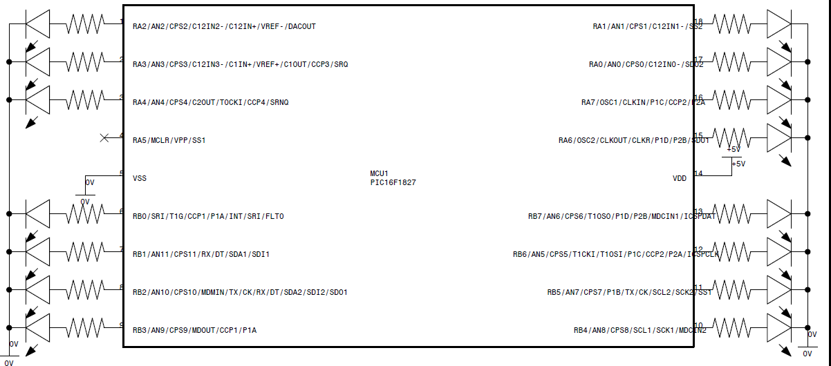
Here's the schematic for the cascading lights circuit. As you can see it's just one MCU and LEDs on all the pins except for pin#4 (RA5) which is an input-only pin. Resistors can be as low as, oh about, 180 ohms for a power supply of 5 volts. You have to watch out for the maximum rating of each pin (25mA if I remember correctly) and the maximum for each PORT.


----

Schematic when using a PIC16F84A

Thursday, October 13, 2011

Video of LED fade in/out

For details of the following vid see yesterday's LED fading using exponentially changing PWM duty cycle. However, because the dimming wasn't as smooth as I wanted it to be, I changed a couple of items.

1. I used 32 pulse width values instead of 16. And so the look-up table for this demo is:
const char PW[] = {0, 0, 1, 1, 1, 2, 2, 3, 4, 5, 6, 7, 9, 10, 12, 15, 18, 22, 26, 31, 37, 44, 53, 63, 75, 90, 107, 127, 151, 180, 214, 255};

2. To preserve the 655ms total time from zero to maximum brightness I halved the timer2 postscale to 1:5.

3. Because of the increase in PW values, the constant in one of the conditional statements had to be changed from 15 to 31:
if (direction && ++i > 31).

LED fading using exponentially changing PWM duty cycle

Not wishing to make the title any longer than it is, I left out the following qualification: Although the duty cycle (pulse width for output high) varies exponentially versus time, the time interval between changes in duty cycle is fixed.

One could I suppose also achieve fading with a linearly changing duty cycle and exponentially changing time interval. Sounds more complicated though.

The problem with fading an LED using PWM is that human perception of brightness is logarithmic, just like our hearing. So changing the PWM duty cycle in a linear fashion (e.g. incrementing or decrementing the duty cycle by 1% every unit time interval) does not result in a perception of linear change in brightness.

The solution is to change the duty cycle exponentially. The following is one formula that provides a way of obtaining a series of duty cycle values with a minimum of 1 and a maximum of 2n, where n is a positive integer. The fact that the numeric base = 2 means the results are perfectly suited to computing values for 8, 16, or 32-bit registers of microcontrollers.

duty cycle = 2x/r

where
x = 1, 2, 3, ..., m-1, m
m = integral number of duty cycle values required.
r is chosen such that 2m/r = maximum duty cycle value

One way to understand x/r is to think of a number of rulers all of the same length--say, 12 inches. One has graduations only in inches. Another has divisions only in half inches (of course two half inches still make an inch). Yet another is marked off in quarter inches. One has one-eighth inch graduations. And another is divided into sixteenths of an inch. x corresponds to the number of graduations/divisions. Hence our 12-inch ruler with quarter-inch divisions has a total of 12 inches x 4 divisions/inch = 48 divisions. And the ruler with one-sixteenth inch graduations has 12 x 16 = 192 divisions. On the other hand, 1/r corresponds to the unit used by our ruler or the distance between graduations. So for inch-graduated ruler, 1/r = 1/1. For the one-eighth-inch-graduated ruler, 1/r = 1/8.

Let's say we are constrained to using an 8-bit register (eg. CCPR1L of the PIC12F615) for our duty cycle values. This means the maximum pulse width value we can specify is 0xFF or 255 decimal. Assume we want to make an LED fade in from zero to full brightness in a relatively short time--less than half a second. Having the LED ramp up 16 values should be sufficient for a visually smooth, seamless fade in. Going back to our ruler, if we employ the ruler with one-inch divisions, we'd have eight values and those values, as per our formula, would be 21/1, 22/1, ... 28/1. But since we'd like 16 different pulse widths, we have to use the half-inch-graduated ruler which has 16 divisions from 1/2 inch to 8 inches. To obtain the actual duty cycle values, we use the formula giving us the following series: 21/2, 22/2, 23/2, ... 215/2, 216/2, or 1.41, 2.00, 2.83, .... 181.02, 256.00. Rounding those numbers off we have the following integral series: 1, 2, 3, 4, 6, 8, 11, 16, 23, 32, 45, 64, 91, 128, 181, 255. Obviously, given our 8-bit constraint, the maximum duty cycle value has to be 255 not 256.

If we wanted 32 pulse width values--perhaps because we are fading the LED over a much longer time interval and 16 values don't provide a smooth enough fade--we'd choose the ruler with quarter-inch divisions. Using the equation we have: 21/4, 22/4, 23/4, 24/4, 25/4, ... 231/4, 232/4. Here's a graph of this example.


Bear in mind that the ruler analogy is only an aid to understanding. Once you get the hang of the equation, you can throw away these imaginary rulers. And contrary to what the ruler examples imply, we're not limited to 2n number of pulse widths (eg. 8, 16, 32, 64). Still taking our maximum duty cycle = 0xFF, we can have, for instance, 24 values: 21/3, 22/3, 23/3, 24/3, 25/3, ... 223/3, 224/3. Or, say, 40 values: 21/5, 22/5, ... 213/5, 214/5, 215/5, ... 239/5, 240/5. Or 56 values: 21/7, 22/7, ... 255/7, 256/7. Notice that for all these examples m/r is still = 8 and so maximum duty cycle value in all these series is 0xFF.

One may, if desired, also use the following slightly modified formula

duty cycle = 2x/r - 1

Using this equation forces the series to start with zero.

Given m = 16, r = 2, and thus a maximum duty cycle value of 216/2 = 0xFF, the series we end up with is: 0, 1, 2, 3, 5, 7, 10, 15, 22, 31, 44, 63, 90, 127, 180, 255. Note how the maximum is neatly the maximum possible for our 8-bit register.

Below is a sample program where an LED alternately fades in and out. The firmware employs a look-up table to change the duty cycle. PWM frequency is 244.14 Hz. This is the minimum PWM frequency obtainable in the PIC12F615 when using its internal oscillator (Fosc = 4MHz). That PWM frequency translates to a period of 4.096ms. Because 4.096ms x 16 duty cycle values is only = 65.5ms, I set timer2 postscaler to 1:10 which has the effect of holding each duty cycle value for 10 periods. With that the amount of time for the LED to go from minimum to maximum duty cycle = 4.096ms x 16 x 10 = 655ms which is slow enough for humans to actually see and appreciate. The downside is that keeping the DC value for 10 periods is noticeable at the lower DC values. The stepwise change is obvious. To remedy this, we can always increase the number of DC values and decrease the timer2 postscale value.

For the PIC12F615,

fPWM = Fosc / [(PR2+1)*4*(T2PS)]

fPWM = PWM frequency
Fosc = frequency of the oscillator
PR2 = PR2 register value
T2PS = timer2 prescale value

PWM period = 1 / fPWM

Pulse width = (CCPR1L:CCP1CON<5:4>)*(T2PS)/Fosc

CCPR1L:CCP1CON<5:4> is a 10-bit number, with the 8-bit MSB in CCPR1L and the 2-bit LSB in CCP1CON<5:4>

In the firmware below CCP1CON<5:4> is = 0. When using the pulse width equation remember to left shift CCPR1L by two places. In other words multiply CCPR1L by 4.

LED is connected to pin P1A/GP2.

/*
LED fading using exponentially changing PWM duty cycle with fixed time interval between changes in duty cycle

October 12 2011

processor = PIC12F615
compiler = mikroC v5.0.0

*/

// computed duty cycle values using the equation INT{[2^(x/r)] + 0.5} - 1
// x = 1, 2, ..., 16
// r = 2
// values are stored in a look-up table in flash rather than RAM
const char PW[] = {0, 1, 2, 3, 5, 7, 10, 15, 22, 31, 44, 63, 90, 127, 180, 255};  

void main()
{
  unsigned char i = 0;
  bit direction;
  
  ANSEL = 0;                 // all pins digital

  // initialize PWM registers
  // see PIC12F615 datasheet DS41302C p.96 for PWM set up procedure
  PR2 = 255;
  CCP1CON = 0b1100;          // enable PWM mode, single output (P1A only)
  CCPR1L = 0;
  PIR1.TMR2IF = 0;           // clear timer2 interrupt flag
  T2CON = 0b1001011;         // timer2 prescale = 1:16, postscale = 1:10
  T2CON.TMR2ON = 1;          // turn on timer2
  TRISIO = 0b0;

  direction = 1;
  while(1)
  {
    if (PIR1.TMR2IF)          // timer2 interrupt flag is set when postscale value is reached 
    {
      if (direction && ++i > 15)
      {
        direction = 0;
        i = 14;
      }
      else if (!direction && --i == 0)
        direction = 1;
      CCPR1L = PW[i];
      PIR1.TMR2IF = 0;
    }
  } // while(1)
} // void main()


----

References:

http://www.instructables.com/community/linear-PWM-LED-fade-with-arduino/
http://www.avrfreaks.net/index.php?name=PNphpBB2&file=printview&t=45080&start=0
http://en.wikipedia.org/wiki/F-number
http://www.mikroe.com/app/webroot/forum/viewtopic.php?f=88&t=22277