Before delving into the electrical characteristics of the Innova's wiper system, let me just provide the wipe time. Using a stopwatch the time for the wiper in intermittent mode to make one complete sweep--wiper goes from park position, sweeps the windshield and back to parking--is approximately 1.3sec.
Here again is a shot of the header pins into which the connectors plug.

After testing the wiper switch module here are the pin assignments I came up with:

Testing included using the resistance/continuity mode of a multimeter to check which pins are electrically connected (practically zero ohms) while trying the various switch settings. Testing also involved plugging the connectors into the module--only partially so I can have access to the headers--turning the ignition key until power is supplied to the wiper circuit and probing the headers with the DMM and trying out the different switch settings on the stalk.
The following summarizes the cold test using the ohmmeter. The presence of links (lines) between pins means those pins are electrically connected at the indicated switch setting.


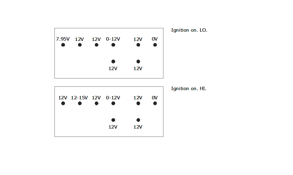
Below are results of the hot test. All voltage values are with reference to chassis ground. The voltage on some pins jump from one value to another or span a range. This is indicated by the nomenclature "x - y". So "0 - 12V" might mean that voltage toggles between these values or that it smoothly but very quickly rises to 12 or declines to 0. Using a DMM did not allow me to determine whether the readings I was getting were indicative of discontinuous or continuous values.

I also checked the PCB disconnected from the connectors and using an ohmeter had the following results.

The yellow box denotes the location of relay on the other side of the board. Hence the solder points within that outline will be the pins on the relay. The solder joint marked "COIL" is inferred from the fact that there is no other pin for the relay coil. Moreover resistance reading from VDD to COIL is 240 ohms--that's within the ballpark for a 12VDC coil.
What is perplexing to me is that there are two relay pins to which W-PP is connected. Why?! This finding has really been very disconcerting. I would've thought that one of the relay contacts would be hooked up to W-LO. Interestingly, if you look at the W-PP track on the left side you'll see that it leads to the top portion of the board to a solder joint. So W-PP is connected to some other component. The mystery deepens.
With the module disconnected and the ignition key turned to supply power to the wiper (with the engine off), I used a DMM set to current measurement to act as a jumper and to measure peak current as well. Here are the results.
| Net 1 | Net 2 | Result of connecting jumper | Maximum Measured Current (amperes) (see footnote) |
|---|---|---|---|
| W-VDD | W-LO | front wiper low speed on continuously but stops as soon as jumper removed--wiper does not park automatically | 3.1 to 4.0A |
| W-PP | W-LO | with wiper initially NOT at parking position, the wiper will move to parking position and then stop; keeping jumper connected does not result in any further action | 3.7 to 6.2A |
| W-VDD | W-HI | front wiper high speed on continuously but stops as soon as jumper removed--wiper does not park automatically | 8.9 to 9.2A |
| W-RW | W-GND | rear wiper turns on continuously and parks automatically when jumper removed | 1.4 to 1.7A |
| W-RM | W-GND | rear mist on as long as jumper connected | 2.0 to 2.6A |
| W-FM | W-GND | front mist on (wiper does not turn on) as long as jumper connected | 2.2 to 2.5A |
Note: Current measurements were made several times. Only MAX values as measured by the 87V were recorded. The range of values per item above are the lowest and highest MAX values.
Given all the above data I have drawn up a provisional schematic diagram. However, it almost certainly is incomplete and contains errors so I won't put it up lest some reader relies upon it as gospel truth.
What can be inferred with high confidence at this time are the following :
- Switching the stalk to LO disconnects W-PP from W-LO and connects W-VDD and W-LO, feeding +12V to the wiper motor's low speed circuit.
- When the stalk is returned to OFF, W-PP is once again connected to W-LO thus automatically parking the wiper.
- When stalk is switched to INT W-PP remains connected to W-LO. The electronic circuit comes into play and switches the on-board relay for about a second every couple of seconds. Judging from the clicks of the relay it is being turned off right at the moment of wiper parking (which makes me wonder yet again how W-PP is being used by the PCB).
- When the stalk is switched to HI, W-PP is not connected to W-LO. W-VDD is connected to W-HI thus supplying +12V to the wiper motor's high speed circuit.
- When stalk is pushed all the way up (switched to MIST--this is a mislabel on Toyota's part since it doesn't turn on the spray) the spring-loaded switch is engaged and W-PP is disconnected from W-LO while W-VDD is connected to W-LO thus supplying +12V to the wiper motor's low speed circuit. Releasing the stalk returns it to OFF position and thus W-PP gets connected to W-LO and the wiper parks automatically.
- From the OFF position, when stalk knob is turned counterclockwise (i.e., turning it toward the driver) to the rear windshield spray icon, W-RM is grounded (connected to W-GND) turning on rear mist motor.
- From the off position, when stalk knob is turned clockwise (i.e., turned toward the dashboard) one notch to ON, W-RW is grounded (connected to W-GND) switching on the rear wiper motor.
- With the rear wiper on, when the stalk knob is turned clockwise to the second rear windshield spray icon, both W-RW and W-RM are connected to W-GND, hence both rear wiper and rear mist are switched on. This is a spring-loaded setting and releasing the knob will return the knob to the rear-wiper-on position and the rear mist motor will be switched off.
- When spring-loaded stalk is pulled toward the driver W-FM is connected to ground via W-GND thus turning on the front mist motor. Because W-FM is connected to the PCB (see labeled PCB pic above), the circuit board most probably senses the level change from 12 to 0 volts. After a brief delay (~0.5sec) from the start of the mist the relay is turned on hence switching on the low speed motor circuit. The relay is kept on for several seconds so that the wiper makes at least three wipes.
In Part 3 I'll discuss a microcontroller-based variable intermittent wiper circuit for the Innova and provide a full listing of the firmware.
Thank you for the information. I was actually diagnosing the part and your diagrams helped out.
ReplyDelete