Just stumbled on the following treasure. The National Programme on Technology Enhanced Learning (NPTEL) has hundreds of hours of recorded lectures on electronics and electrical engineering and other subjects as well. Watch them all on Youtube.
I just love lectures ... sans the exams of course.
Thursday, July 23, 2009


Tuesday, June 30, 2009
You don't get what you don't pay for
Sigh. Repeat after me: You can't have your cake and eat it too. You can't have your cake and ....
I've been test driving the Hi-Tech C Pro compiler for the PIC MCUs and much as I am thrilled that it works under MPLAB and is being offered completely free (Lite version) without firmware size or time period restrictions, I must say that the lack of optimization in the freeware version is rather depressing. The code it produces is quite inefficient.
For instance, for the PIC 10F20x series, for the given a static global variable the C statement "POTATO++" or "++POTATO" is translated into assembly by Hi-Tech Lite as follows:
MOVLW 0x1
MOVWF 0x13
MOVF 0x13, W
ADDWF 0x1e, F
Am scratching my head. Why the two middle instructions? Why not cut to the chase and have:
MOVLW 0x1
ADDWF 0x1e, F
Or better yet, why not just
INCF 0x1e, F
Wasting two to three bytes and instruction cycles in an MCU that has only 256 / 512 words of program space is just crazy.
I know I'm making a hasty conclusion but this one example of utter wastefulness shows me why this is freeware. I'm wondering how the versions with "Omniscient Code Generation" will compile the above. Hopefully you do get what you pay for.
I've been test driving the Hi-Tech C Pro compiler for the PIC MCUs and much as I am thrilled that it works under MPLAB and is being offered completely free (Lite version) without firmware size or time period restrictions, I must say that the lack of optimization in the freeware version is rather depressing. The code it produces is quite inefficient.
For instance, for the PIC 10F20x series, for the given a static global variable the C statement "POTATO++" or "++POTATO" is translated into assembly by Hi-Tech Lite as follows:
MOVLW 0x1
MOVWF 0x13
MOVF 0x13, W
ADDWF 0x1e, F
Am scratching my head. Why the two middle instructions? Why not cut to the chase and have:
MOVLW 0x1
ADDWF 0x1e, F
Or better yet, why not just
INCF 0x1e, F
Wasting two to three bytes and instruction cycles in an MCU that has only 256 / 512 words of program space is just crazy.
I know I'm making a hasty conclusion but this one example of utter wastefulness shows me why this is freeware. I'm wondering how the versions with "Omniscient Code Generation" will compile the above. Hopefully you do get what you pay for.
Monday, June 22, 2009
More on that timer
Modifications made to the timer:

MCU = Microchip PIC 16F785
Q1,Q2 = S9012 PNP transistor
Q3 = 2N7000 MOSFET transistor
XTAL = 32.768kHz crystal
7SEG LED = ELD-306IDB dual 7-segment LED common anode
all resistors 1/4Watt 5%
I've installed the timer in my aunt's kitchen. Much to my chagrin the volume of the buzzer was not close to earsplitting. Although as with any sonalert buzzer, it will surely be heard tens of meters away.
- New "wall wart" power supply. Oscilloscope test of output shows it has no filter capacitor so a 470uF 25V electrolytic was added to the board. No-load voltage with filter cap was >20VDC.
- Added a LM78L12ACZ and LM78L05ACZ voltage regulator
- A 1N4002 was added as a safety feature in case power supply polarity is inadvertently reversed.

MCU = Microchip PIC 16F785
Q1,Q2 = S9012 PNP transistor
Q3 = 2N7000 MOSFET transistor
XTAL = 32.768kHz crystal
7SEG LED = ELD-306IDB dual 7-segment LED common anode
all resistors 1/4Watt 5%
I've installed the timer in my aunt's kitchen. Much to my chagrin the volume of the buzzer was not close to earsplitting. Although as with any sonalert buzzer, it will surely be heard tens of meters away.
Tuesday, June 16, 2009
The timer's dead; long live the timer!
Two years ago I installed a countdown timer at my sister's apartment. The user can set the time anywhere from 1 to 99 minutes. After the countdown is over a Sonalert buzzer will blare. The alarm has three stages, each with successively higher duty cycle. It begins with gentle fractional-second beeps so as not cause a heart attack. Each stage runs for approximately 10 seconds.
The engine that drives the timer is a 20-pin Microchip PIC 16F785 microcontroller. For user interface the time has a two-digit 7-segment LED display and two momentary contact buttons. Pressing the UP/DOWN button for a fraction of a second will increment/decrement the readout by one; keeping it depresed will increment/decrement the reading by 10. If the readout is not zero and no button is pressed for around 4 seconds, countdown begins. Once countdown has started either button will abort the count and readout will be zeroed. If countdown is allowed to run its course and the buzzer starts sounding, either button will turn the alarm off. When readout is "0" for some 16 seconds, readout will be blanked and MCU will go to sleep. Pressing either button will wake it up.
Although my sis has almost never used the timer (all that effort soldering the dang thing for nothing!) I just found out it doesn't work! The only reason I discovered it's on the blink is that I took it down and was going to give it to my aunt. She found out I have a timer in my home (practically the same design but has some improvements) and she says she needs one too.
To cut to the chase, it turns out the power supply is dead. The PSU is an Ericsson cell phone charger model AA21990 which has an output of 5.1V 450mA. To add to the trouble, while testing the timer using a working PSU (not an Ericsson) I discovered that the MCU was running very warm. Now that's bad! The timer was working fine, meaning the MCU was still running the firmware, but somehow or other there was a short or a quasi short somewhere. I inspected the solder side of the board but it was fine. I cleaned the board just to make sure. Finally in desperation I took out a new 16F785, burned in the firmware, and dropped it in the DIP socket. Well, what do you know? The original MCU was fried as well!
My guess is that the PSU must've taken the MCU with it when it burned out.
I tried reprogramming the MCU. This PICkit2 says it has a Vpp problem. At some point it couldn't even detect the device. Guess that's it for that chip. Its time is up!
I'm modifying the circuit before installing it in my aunt's home. Instead of being powered by 5VDC the buzzer will now be operated at 12 volts. That increases the alarm volume considerably so it can be heard even in the next room with the door closed. It's going to be earsplitting in the kitchen.
The engine that drives the timer is a 20-pin Microchip PIC 16F785 microcontroller. For user interface the time has a two-digit 7-segment LED display and two momentary contact buttons. Pressing the UP/DOWN button for a fraction of a second will increment/decrement the readout by one; keeping it depresed will increment/decrement the reading by 10. If the readout is not zero and no button is pressed for around 4 seconds, countdown begins. Once countdown has started either button will abort the count and readout will be zeroed. If countdown is allowed to run its course and the buzzer starts sounding, either button will turn the alarm off. When readout is "0" for some 16 seconds, readout will be blanked and MCU will go to sleep. Pressing either button will wake it up.
Although my sis has almost never used the timer (all that effort soldering the dang thing for nothing!) I just found out it doesn't work! The only reason I discovered it's on the blink is that I took it down and was going to give it to my aunt. She found out I have a timer in my home (practically the same design but has some improvements) and she says she needs one too.
To cut to the chase, it turns out the power supply is dead. The PSU is an Ericsson cell phone charger model AA21990 which has an output of 5.1V 450mA. To add to the trouble, while testing the timer using a working PSU (not an Ericsson) I discovered that the MCU was running very warm. Now that's bad! The timer was working fine, meaning the MCU was still running the firmware, but somehow or other there was a short or a quasi short somewhere. I inspected the solder side of the board but it was fine. I cleaned the board just to make sure. Finally in desperation I took out a new 16F785, burned in the firmware, and dropped it in the DIP socket. Well, what do you know? The original MCU was fried as well!
My guess is that the PSU must've taken the MCU with it when it burned out.
I tried reprogramming the MCU. This PICkit2 says it has a Vpp problem. At some point it couldn't even detect the device. Guess that's it for that chip. Its time is up!
I'm modifying the circuit before installing it in my aunt's home. Instead of being powered by 5VDC the buzzer will now be operated at 12 volts. That increases the alarm volume considerably so it can be heard even in the next room with the door closed. It's going to be earsplitting in the kitchen.
Monday, May 25, 2009
Firmware keeps an eye on the health of water level sensors
The sensor diagnostics routine I programmed into the water system I installed some two years ago finally paid off today. The alarm went off and the LEDs were flashing like crazy indicating that a sensor problem had been detected. For the particular fault that befell the system today, had there been no sensor diagnostics the tank wouldn't have filled to maximum. At most it would fill to 75%. And I wouldn't have known that a fault condition existed until I accidentally notice that the indicator LEDs aren't right.
Briefly, here's a description of the water system. There are two water tanks, one located at the ground level and the other at the roof deck of a two-storey house. Water from the mains fills the ground level tank (GT) via a solenoid valve whenever it's not full. The roof deck tank (RT) is normally filled by another solenoid valve, but when water pressure is insufficient to fill it within a predetermined amount of time then a pump kicks in to do the job. There are sensors in both tanks. Two types are employed. The primary sensors are simple stainless tubes of varying lengths to detect water at different levels of the tank. The other type of sensor is a float switch and is used to detect a full tank and tank overflow condition. The float has a magnet inside which closes a reed switch in the body of the assembly whenever it's buoyed up by water. For both tanks there are sensors for water levels of 25%, 50%, 75% and 100%. RT has an additional sensor to detect overflow condition (this is simply a float switch located above the 100% water level sensor).

Above is a stylized diagram and schematic of the sensor setup inside the roof deck tank. Pull up resistors (located in the control panel) mean that output is low when sensor is submerged in water.
The control panel is located adjacent to GT. The enclosure contains all of the electronics, actuator control circuitry (to switch the DC solenoid valves and 500-Watt AC pump), and power supply. It also has indicator LEDs arranged to mimic two bar graphs, indicating the water levels for each of the tank as well as LEDs for the status of the solenoid valves and pump. There are also LEDs for RT overflow condition and empty-tank condition for both GT and RT. A Sonalert buzzer provides the audible alarm.
MCU is a PIC16F627A. Sensor outputs from both tanks are filtered by a simple RC passive low pass filter before being fed to a 74AC540 octal inverting buffer whose outputs then drive both the LEDs and the input pins of the MCU.
I'll skip details of the other parts of the firmware and simply discuss the sensor diagnostics part. If I recall correctly, years ago before upgrading the circuit up to an MCU-based system there had been at least one instance when one of the gauge-24 wires to the stainless steel sensors snapped off. Can't remember what havoc that wreaked but it was a fault condition nevertheless that eventually had to be repaired. The diagnostics algorithm that's been included in the firmware is based on the fact that depending on the water level, there are combinations of sensors that are "on", so to speak, which are valid and some which are not. And by "on" here we mean that the sensor is submerged in water. The diagnostic routine simply checks whether the current combination of sensors that are on is valid. If it is then the program just continues. If the combination is invalid then the diagnostics routine keeps looping back and checking the sensors until the fault is corrected.
For instance when the 100% water level probe is on then obviously all the other sensors must be on too. If any are not then a sensor fault condition exists. So, if the 25, 50, and 100% water level sensors all purport to detect water but the 75% sensor doesn't, something must be wrong.
And that was precisely the fault condition this morning. Which led to the system automatically shutting off all the valves and pump and switching on audible and visual alarms which in turn sent me into panic mode. Given that the 75% level indicator LED for the upper tank was off while the 100% level LED was on, I jumped to the conclusion that it must be a loose or corroded connection. And I then proceeded to check the 75% level wiring and wire connections. Turned out I was wrong. It was in fact the 100% level sensor that was on the blink. And it wasn't even an electrical fault. The sensor is a float switch and apparently the float had become stuck--just slightly. Since the water level at that time was below the 75% sensor, the float actually dropped on its own while I was checking the stainless steel sensors. Algae or light mud could've been the culprit.
Briefly, here's a description of the water system. There are two water tanks, one located at the ground level and the other at the roof deck of a two-storey house. Water from the mains fills the ground level tank (GT) via a solenoid valve whenever it's not full. The roof deck tank (RT) is normally filled by another solenoid valve, but when water pressure is insufficient to fill it within a predetermined amount of time then a pump kicks in to do the job. There are sensors in both tanks. Two types are employed. The primary sensors are simple stainless tubes of varying lengths to detect water at different levels of the tank. The other type of sensor is a float switch and is used to detect a full tank and tank overflow condition. The float has a magnet inside which closes a reed switch in the body of the assembly whenever it's buoyed up by water. For both tanks there are sensors for water levels of 25%, 50%, 75% and 100%. RT has an additional sensor to detect overflow condition (this is simply a float switch located above the 100% water level sensor).

Above is a stylized diagram and schematic of the sensor setup inside the roof deck tank. Pull up resistors (located in the control panel) mean that output is low when sensor is submerged in water.
The control panel is located adjacent to GT. The enclosure contains all of the electronics, actuator control circuitry (to switch the DC solenoid valves and 500-Watt AC pump), and power supply. It also has indicator LEDs arranged to mimic two bar graphs, indicating the water levels for each of the tank as well as LEDs for the status of the solenoid valves and pump. There are also LEDs for RT overflow condition and empty-tank condition for both GT and RT. A Sonalert buzzer provides the audible alarm.
MCU is a PIC16F627A. Sensor outputs from both tanks are filtered by a simple RC passive low pass filter before being fed to a 74AC540 octal inverting buffer whose outputs then drive both the LEDs and the input pins of the MCU.
I'll skip details of the other parts of the firmware and simply discuss the sensor diagnostics part. If I recall correctly, years ago before upgrading the circuit up to an MCU-based system there had been at least one instance when one of the gauge-24 wires to the stainless steel sensors snapped off. Can't remember what havoc that wreaked but it was a fault condition nevertheless that eventually had to be repaired. The diagnostics algorithm that's been included in the firmware is based on the fact that depending on the water level, there are combinations of sensors that are "on", so to speak, which are valid and some which are not. And by "on" here we mean that the sensor is submerged in water. The diagnostic routine simply checks whether the current combination of sensors that are on is valid. If it is then the program just continues. If the combination is invalid then the diagnostics routine keeps looping back and checking the sensors until the fault is corrected.
For instance when the 100% water level probe is on then obviously all the other sensors must be on too. If any are not then a sensor fault condition exists. So, if the 25, 50, and 100% water level sensors all purport to detect water but the 75% sensor doesn't, something must be wrong.
And that was precisely the fault condition this morning. Which led to the system automatically shutting off all the valves and pump and switching on audible and visual alarms which in turn sent me into panic mode. Given that the 75% level indicator LED for the upper tank was off while the 100% level LED was on, I jumped to the conclusion that it must be a loose or corroded connection. And I then proceeded to check the 75% level wiring and wire connections. Turned out I was wrong. It was in fact the 100% level sensor that was on the blink. And it wasn't even an electrical fault. The sensor is a float switch and apparently the float had become stuck--just slightly. Since the water level at that time was below the 75% sensor, the float actually dropped on its own while I was checking the stainless steel sensors. Algae or light mud could've been the culprit.
Wednesday, May 13, 2009
SIRCS: The real score
While researching the Sony SIRCS protocol (some say it's "SIRC") for infrared remote controls, I got somewhat confused as to the pulse widths for the ones and zeroes. You see some say that a zero is represented by a 0.8ms pulse width while a one is 1.2ms long, with a 0.4ms low between bits. On the other hand, there are others who say that it's 0.6ms and 1.2ms respectively with a 0.6ms space between bits. So who's right? Unfortunately Sony doesn't have an official online document on the protocol (or at least I haven't found one yet) to clear things up.
After more research, I've come to believe that it is in fact the latter that's correct--0.6ms for a zero and 1.2ms for a one. Let me just provide some references for this.
Jon Williams in his article "Creating Time-Lapse Video" in the March 2009 issue of Nuts and Volts writes: "The SIRCS signal has a 2.4 millisecond start bit, '1' bits are 1.2 milliseconds wide, and '0' bits are 0.6 milliseconds wide — and every bit is spaced by a 0.6 millisecond off-time."
Likewise, according to Microchip Application Note AN1064 entitled "IR Remote Control Transmitter" the SIRCS protocol has on time (bit period) of 1.2ms for a logical "1" and 0.6ms for a logical "0."
In his excellent site on infrared remote controls San Bergmans tells us that, "the pulse representing a logical '1' is a 1.2ms long burst of the 40kHz carrier, while the burst width for a logical '0' is 0.6ms long. All bursts are separated by a 0.6ms long space interval."
Finally, co-author Jack Smith, in PIC Microcontrollers: Know It All (Newnes, 2008) provides a waveform diagram for the SIRCS protocol, again showing that same bit periods.
Be that as it may, the three Sony IR remote controls that I've tested do in fact have on times of around 0.8ms to represent "0." I got 1.4ms for "1." I used a 38kHz IR receiver but the SIRCS operates with a 40kHz carrier frequency. That's a 5% difference. I don't know if that significantly affects the test results.
After more research, I've come to believe that it is in fact the latter that's correct--0.6ms for a zero and 1.2ms for a one. Let me just provide some references for this.
Jon Williams in his article "Creating Time-Lapse Video" in the March 2009 issue of Nuts and Volts writes: "The SIRCS signal has a 2.4 millisecond start bit, '1' bits are 1.2 milliseconds wide, and '0' bits are 0.6 milliseconds wide — and every bit is spaced by a 0.6 millisecond off-time."
Likewise, according to Microchip Application Note AN1064 entitled "IR Remote Control Transmitter" the SIRCS protocol has on time (bit period) of 1.2ms for a logical "1" and 0.6ms for a logical "0."
In his excellent site on infrared remote controls San Bergmans tells us that, "the pulse representing a logical '1' is a 1.2ms long burst of the 40kHz carrier, while the burst width for a logical '0' is 0.6ms long. All bursts are separated by a 0.6ms long space interval."
Finally, co-author Jack Smith, in PIC Microcontrollers: Know It All (Newnes, 2008) provides a waveform diagram for the SIRCS protocol, again showing that same bit periods.
Be that as it may, the three Sony IR remote controls that I've tested do in fact have on times of around 0.8ms to represent "0." I got 1.4ms for "1." I used a 38kHz IR receiver but the SIRCS operates with a 40kHz carrier frequency. That's a 5% difference. I don't know if that significantly affects the test results.
Sunday, May 3, 2009
Philips IR remote control
The only Philips IR remote control (IRRC) that I have is one for the 20PT3882 TV.

I needed to "see" the transmission of the above IRRC and measure the pulse widths. Unfortunately until recently I didn't have a digital oscilloscope to capture the very first transmission--the first packet. So I rigged up a PIC16F616 microcontroller and an LCD to display the pulse widths of the highs and lows. I used an Osram SFH5110-38 IR receiver (IRRX) to detect the IR signal (I don't have a 36kHz receiver so this Osram just had to do--I don't know how much this 5% difference impacts the results).
In a nutshell, I programmed the MCU to issue an interrupt every time the signal on the pin connected to the IRRX output changed state--high to low or low to high. One of the MCU timers is then used to measure how long the signal was high/low. This value is stored in memory. After all the bits have been collected, the pulse widths are sequentially displayed on the LCD.
I was not very confident that my setup would produce the desired results. To my relief, it actually worked well. When I aimed the IRRC at the IRRX and pressed a button, the LCD produced a stream of numbers (in microseconds/milliseconds) which corresponded to how long the pulses were high/low. The values I got were pretty much consistent with the Philips RC5 protocol, with short pulse widths of 0.800 to 0.944ms and long pulse widths of 1.712 to 1.840ms. The protocol says it should be 0.889ms and 1.778ms respectively.
I tested the digit buttons and they conformed to the protocol pretty well.
But I was confounded when I tried the cursor keys (the four blue buttons in the photo above). The LCD started spewing rubbish. Some long pulses were over 2.5ms long and some short ones were less than 0.5ms. Something was not right. Either this unit was not using the RC5 protocol (which I doubt) or my MCU setup was misreading the signals.
With the DSO I've finally put to rest my doubts about whether the transmissions were being faithfully rendered by the MCU. True enough at times pulse widths were off by over 30% or even 50%. I really don't know if this particular unit is a lemon or what.
Here are some examples of out of spec pulses when the cursor keys are pressed. The pulse train on the upper half of each picture is one IR transmission (one packet). The lower half shows a zoomed-in portion. Vertical lines on the lower half are the DSO's cursors. You can read off the deltaX at the upper right. That's the measured pulse width.


The two pictures above are of the same transmission. I just moved the cursors. The two pictures below are from another transmission. Again, I moved the cursor lines.

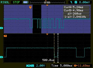
Apparently, the very long pulse width (happens when IRRX output is high) occurs most frequently when the IRRC is within a meter of the IRRX. The closer the IR transmitter is to the receiver the greater the distortion in the received signal. At greater distances it seldom if ever occurs. The very short pulse widths (happens when IRRX output is low) seems to occur at whatever distance.
For info on the Philip's RC5 protocol see:
AN10210 Using the Philips 87LPC76x microcontroller as a remote control transmitter
AN1064 IR Remote Control Transmitter
San Bergman's IR remote control pages

I needed to "see" the transmission of the above IRRC and measure the pulse widths. Unfortunately until recently I didn't have a digital oscilloscope to capture the very first transmission--the first packet. So I rigged up a PIC16F616 microcontroller and an LCD to display the pulse widths of the highs and lows. I used an Osram SFH5110-38 IR receiver (IRRX) to detect the IR signal (I don't have a 36kHz receiver so this Osram just had to do--I don't know how much this 5% difference impacts the results).
In a nutshell, I programmed the MCU to issue an interrupt every time the signal on the pin connected to the IRRX output changed state--high to low or low to high. One of the MCU timers is then used to measure how long the signal was high/low. This value is stored in memory. After all the bits have been collected, the pulse widths are sequentially displayed on the LCD.
I was not very confident that my setup would produce the desired results. To my relief, it actually worked well. When I aimed the IRRC at the IRRX and pressed a button, the LCD produced a stream of numbers (in microseconds/milliseconds) which corresponded to how long the pulses were high/low. The values I got were pretty much consistent with the Philips RC5 protocol, with short pulse widths of 0.800 to 0.944ms and long pulse widths of 1.712 to 1.840ms. The protocol says it should be 0.889ms and 1.778ms respectively.
I tested the digit buttons and they conformed to the protocol pretty well.
But I was confounded when I tried the cursor keys (the four blue buttons in the photo above). The LCD started spewing rubbish. Some long pulses were over 2.5ms long and some short ones were less than 0.5ms. Something was not right. Either this unit was not using the RC5 protocol (which I doubt) or my MCU setup was misreading the signals.
With the DSO I've finally put to rest my doubts about whether the transmissions were being faithfully rendered by the MCU. True enough at times pulse widths were off by over 30% or even 50%. I really don't know if this particular unit is a lemon or what.
Here are some examples of out of spec pulses when the cursor keys are pressed. The pulse train on the upper half of each picture is one IR transmission (one packet). The lower half shows a zoomed-in portion. Vertical lines on the lower half are the DSO's cursors. You can read off the deltaX at the upper right. That's the measured pulse width.


The two pictures above are of the same transmission. I just moved the cursors. The two pictures below are from another transmission. Again, I moved the cursor lines.


Apparently, the very long pulse width (happens when IRRX output is high) occurs most frequently when the IRRC is within a meter of the IRRX. The closer the IR transmitter is to the receiver the greater the distortion in the received signal. At greater distances it seldom if ever occurs. The very short pulse widths (happens when IRRX output is low) seems to occur at whatever distance.
For info on the Philip's RC5 protocol see:
AN10210 Using the Philips 87LPC76x microcontroller as a remote control transmitter
AN1064 IR Remote Control Transmitter
San Bergman's IR remote control pages
Subscribe to:
Posts (Atom)