Sunday, January 24, 2010

Finding the resistor values in a voltage divider

Am currently designing an instrumentation amplifier circuit that requires two different voltages for level shifting (Vcc/2 and Vcc/10). To obtain these voltages I'm using a simple voltage divider using three resistors. I tried finding the values by via trial and error--plugging the voltage divider equation into a spreadsheet and manually trying different values to get the correct voltages as well as values available for 5% resistors. Well, after some half dozen tries, I threw my hands up in the air. It's just too clumsy to do it that way. So I took pen and paper and started deriving the necessary equations. Here are the results.


Given the above circuit and the value of either A, B, or C, and given f and g, we want to find the values of the other two resistors. f and g are defined as follows:


You will notice that if we multiply Eq.1 and Eq.2 by source voltage VS on either side of the equation we get the voltage divider equations. But we don't need VS to find the resistor values.

We first solve for A in both equations.

For Eq.1


For Eq.2


Equating Eq.3 and Eq.4 we have


We then solve for either B or C. Let's do B first.


Thus,


Using Eq.3 and substituting Eq.6 for C we have


Thus,


Using Eq.3 and substituting Eq.5 for B we have


Thus,


Eq.3 and Eq.4 gave us A in terms of B and C. Using these sames equations we can also find B in terms of A and C, and C in terms of A and B. The derivation is trivial so only the results are provided below.


So there you have it--all the equations necessary to find the resistor values given any of them. In my case I still needed the spreadsheet to help me find values that are commercially available. I plugged in a couple of the equations in the spreadsheet, and then by choosing different values for B given f = 2 and g = 10, I eventually got A = 15K, C = 3K, given B = 12K. Those are values readily available for 5% resistors.


---

Note: I used Codecogs' LaTeX Equation Editor to produce the images for the equations above. Am a newbie to Latex and have no idea how to pad spaces to move "Eq." towards the right. With a bit of trial and error I found that placing x number of "\ ", that's forward slash and then a blank space, will force x number of blank spaces.

Sunday, January 3, 2010

Raindrop Christmas lights

During a recent visit to the malls I saw what I would describe as raindrop type Christmas lights. Instead of bulbs there were these 5-inch transparent glass or plastic tubes which housed white LEDs. A cable ran from tube to tube. The LEDs started lighting from the top and simulated a falling raindrop. One LED would light, then two, then three, ... By the time the fifth LED was on, the first was off. The sixth would light and the second go out. So there was the illusion of a segment of four LEDs racing down. This went pretty fast--some two seconds.

I didn't bring my camera and I completely forgot that my phone has a camera and so I don't have a picture to show. I googled "raindrop christmas lights" and fortunately found this.


As far as I can see from this photo this tube has around twice more LEDs than the one I saw which had around 15 to 20 of what looked like 5mm white LEDs.

Each tube has its own controller chip since the tubes weren't lighting up at the same time. More evidently, there was no big cable running from tube to tube which you'd expect if these tubes were centrally controlled--what a cabling nightmare!

What intrigues me is the smallness of the unit and what must be a limited number of parts on that long but very narrow board. I can't imagine not having some cap for filtering/bypassing so it must have high value ceramics and/or tiny electrolytics. I presume that the cable is merely for 3.3 to 5V power. And the resistors for the LED? Chip resistors? Could these LEDs have internal resistors?

As for the controller chip, I'm wondering if they're using an MCU or some other programmable IC. Could each LED be switched by a dedicated pin? Or are they charlieplexed/multiplexed?

In the lights that I saw the last LED at the bottom remains lit for about a second and a half, fading out till it's off. Beautiful effect. PWM is being used of course.

This is a most interesting product and I'd love to take one apart and see its design. It can easily be effected using an MCU. Firmware is simple. Engineering a board this compact is the bigger challenge.

Charlie to the rescue

Am working on a circuit that I want driven by an 8-pin PIC microcontroller. A 10-pin PIC would be great but such a part I can only dream of. The next available PIC has 14 pins and would be overkill for the project. The thing is I have 5 output devices to switch and only three output lines left since two other I/O lines are dedicated to analog signals while another pin is input-only (the MCLR pin) which is completely feckless for the application I'm working on. So the dilemma I'm faced with is how to switch four LEDs and one transistor with just these three pins.

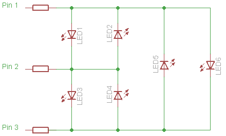
Solution? Call in Charlie [see endnote]. Charlieplexing is the technique of taking advantage of the the tri-state mode of MCU I/O pins. By configuring the pins as input (high Z or high impedance), output high, or output low, a lot more LEDs can be switched than there are pins. In fact the number of LEDs that can be accommodated = n2 - n, where n = number of I/O pins. Given the three pins that I have a maximum of 32 - 3 = 6 LEDs can be switched individually:


However, I also need to get the transistor in as well. And I don't want it getting switched on along with any of the LEDs. Well, lucky me. Turns out that with that constraint I can charlieplex a maximum of four LEDs and this transistor. Here's the circuit that I ended up with (click to enlarge):


Without transistor Q, LR anode can be connected to line2 and its cathode to com and only one current limiting resistor (on com pin) is necessary. With this configuration I tried designing in two resistors, but it seems three are required. Each resistor is half the value since two resistors are conducting whenever an LED is on.

The following table shows the I/O pin configuration necessary to switch on the different LEDs and transistor. 1 = output high, 0 = output low, Z = input mode
part on | line1 | com | line2
--------+-------+-----+--------
LG | 1 | 0 | Z
LY | 0 | 1 | Z
LO | Z | 1 | 0
LR | 1 | Z | 0
Q | Z | Z | 1
To turn off all the devices just turn all pins into inputs. Yes, the gate of the MOSFET is floating when line2 is high-Z, so a pull-down resistor may be necessary.


Notes:

I actually didn't know the name of this technique when I read about it some two years ago in Microchip's 8-pin PIC Tips 'n Tricks literature. By the way, here's the latest Tips 'n Tricks. It's actually a compilation of all existing TnTs. Great resource.