Solution? Call in Charlie [see endnote]. Charlieplexing is the technique of taking advantage of the the tri-state mode of MCU I/O pins. By configuring the pins as input (high Z or high impedance), output high, or output low, a lot more LEDs can be switched than there are pins. In fact the number of LEDs that can be accommodated = n2 - n, where n = number of I/O pins. Given the three pins that I have a maximum of 32 - 3 = 6 LEDs can be switched individually:
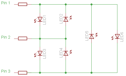
However, I also need to get the transistor in as well. And I don't want it getting switched on along with any of the LEDs. Well, lucky me. Turns out that with that constraint I can charlieplex a maximum of four LEDs and this transistor. Here's the circuit that I ended up with (click to enlarge):

Without transistor Q, LR anode can be connected to line2 and its cathode to com and only one current limiting resistor (on com pin) is necessary. With this configuration I tried designing in two resistors, but it seems three are required. Each resistor is half the value since two resistors are conducting whenever an LED is on.
The following table shows the I/O pin configuration necessary to switch on the different LEDs and transistor. 1 = output high, 0 = output low, Z = input mode
part on | line1 | com | line2To turn off all the devices just turn all pins into inputs. Yes, the gate of the MOSFET is floating when line2 is high-Z, so a pull-down resistor may be necessary.
--------+-------+-----+--------
LG | 1 | 0 | Z
LY | 0 | 1 | Z
LO | Z | 1 | 0
LR | 1 | Z | 0
Q | Z | Z | 1
Notes:
I actually didn't know the name of this technique when I read about it some two years ago in Microchip's 8-pin PIC Tips 'n Tricks literature. By the way, here's the latest Tips 'n Tricks. It's actually a compilation of all existing TnTs. Great resource.
No comments:
Post a Comment