In the following screenshots,
Channel 1 (yellow) = Line A
Channel 2 (cyan) = Line B
Math channel (purple) = A - B
Overshoots and undershoots are clearly visible during high/low transitions. In all probability these are due to signal reflections in the cable.

Zooming in:

With math channel turned on:

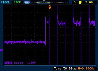
Channels 1 and 2 are turned off and vertical scale of math is decreased from 5 to 2V/division:

Vertical scale reduced to1V/div. Look at the left half of the trace. When transmitter is off A - B is approximately 1.0V. (Adjusting the vertical scale to <1V/div and using cursors, I was able to take a more accurate reading of 1.08V. With only one receiver connected A-B = 1.50V). Since this is >200mV pin R of the receivers will be high--the mandatory and expected line idle state.
Here are zoomed in views of over- and undershoots. The ringing dies out well before half a bit width. The first screenshot shows line A going from low to high. The second shows line A going from high to low. Note the different horizontal scales--500ns in the first, 200ns in the second.


My Rigol scope only has two channels so in the following screenshots
Channel 1: Line A
Channel 2: SN75176B pin R

Even with the ringing there are no errors in the output of the receiver, although undershoot does occur occasionally in pin R output (the Rigol is prone to aliasing, so there may in fact be very high frequency ringing which isn't showing up at this horizontal scale.)
With horizontal scale reduced, we get to see details of undershoots on pin R.


Overshoots when pin R goes from low to high are probably less frequent--I haven't been able to capture any yet.

Just to be fair to line B I let
Channel 1: Line B
Channel 2: SN75176B pin R


What I'd like to do in the future is to increase the baud rate to >100kbps and increase the cable length. Should be interesting to see how bad the ringing will get. And how it will affect data integrity. Something like the following is expected.

That's from a lab test performed by Texas Instruments. Baud rate was 200kbps. 100 feet of Bertek 100-ohm AWG24 twisted pair cable was used. There was one driver and only one receiver (TI AM26C31C and AM26C32C).
No comments:
Post a Comment