Just as a challenge I wanted to emulate the effect using ordinary white LEDs and a microcontroller. After some trial and error I got the firmware working. I'm sure it could be improved upon and different variations could be implemented. For instance as in the second vid above, the cascade could be made without PWM, leaving fading for the very last LED.
So here's a vid of the breadboarded circuit. The firmware that drives it follows. If anyone will be so kind enough to donate a real video cam the pic quality can be greatly enhanced :-)
/*
Cascading (Snowfall or Meteor) LED Lights
October 16 2011
processor = PIC16F1827
compiler = mikroC v5.0.0
(configuration settings -- copied from mikroC's "Edit Project" window)
CONFIG1 :$8007 : 0x0F84
CONFIG2 :$8008 : 0x1613
*/
// if using different PORT pins just change the assignments below
// the firmware does not need to be edited
#define led1 LATA.f1 // led1 is the first LED to be lit (topmost LED of the cascade)
#define led2 LATA.f0
#define led3 LATA.f7
#define led4 LATA.f6
#define led5 LATB.f7
#define led6 LATB.f6
#define led7 LATB.f5
#define led8 LATB.f4
#define led9 LATB.f3
#define led10 LATB.f2
#define led11 LATB.f1
#define led12 LATB.f0
#define led13 LATA.f4
#define led14 LATA.f3
#define led15 LATA.f2 // led15 is the last LED to be lit (bottom LED of the cascade)
#define lastled led15 // this is used in the Twinkle() function
// following used for twinkle effect
#define fadeintime 2 // number of PWM periods for each pulse width during fade in from min to max brightness
#define fadeouttime 7 // number of PWM periods for each pulse width during fade out from max to min brightness
#define twinkle_delay 1 // deciseconds between the end of the cascade and beginning of twinkle effect
// during this time led15 is off
#define cascade_delay 20 // deciseconds between cascades. during this time all LEDs are off
// time begins after Twinkle()
#define t0_ini 256-128 // TMR0 initialize value every time it overflows
#define t1h_ini 256-98 // TMR1H initialize value every time it overflows
#define cascadetime 10 // number of cycles (PWM periods) per stage
#define maxstage 22 // maximum number of stages
// a stage is when a set of LEDs are lit
// each successive stage moves the cascade by one LED
#define int1 bit
#define int8 unsigned char
#define int16 unsigned int
#define int32 unsigned long
#define on 1
#define off 0
// ==================================================================================================================
void IniReg()
{
OSCCON = 0b1110000; // 8MHz
TRISA = 0;
TRISB = 0;
ANSELA = 0;
ANSELB = 0;
LATA = 0;
LATB = 0;
T1CON = 0b110000; // prescale = 1:8, timer1 off
// given 8MHz, TMR1H = 98 counts, prescale = 1:8, timer1 tick = ~100ms
} // void IniReg()
// During the start of each PWM period the LEDs that will be "PWMed" for that stage are turned on.
void IniLEDs(int8 STAGE)
{
switch (STAGE)
{
case 1:
led1 = on;
break;
case 2:
led1 = on;
led2 = on;
break;
case 3:
led1 = on;
led2 = on;
led3 = on;
break;
case 4:
led1 = on;
led2 = on;
led3 = on;
led4 = on;
break;
case 5:
led1 = on;
led2 = on;
led3 = on;
led4 = on;
led5 = on;
break;
case 6:
led1 = on;
led2 = on;
led3 = on;
led4 = on;
led5 = on;
led6 = on;
break;
case 7:
led1 = on;
led2 = on;
led3 = on;
led4 = on;
led5 = on;
led6 = on;
led7 = on;
break;
case 8:
led1 = on;
led2 = on;
led3 = on;
led4 = on;
led5 = on;
led6 = on;
led7 = on;
led8 = on;
break;
case 9:
led2 = on;
led3 = on;
led4 = on;
led5 = on;
led6 = on;
led7 = on;
led8 = on;
led9 = on;
break;
case 10:
led3 = on;
led4 = on;
led5 = on;
led6 = on;
led7 = on;
led8 = on;
led9 = on;
led10 = on;
break;
case 11:
led4 = on;
led5 = on;
led6 = on;
led7 = on;
led8 = on;
led9 = on;
led10 = on;
led11 = on;
break;
case 12:
led5 = on;
led6 = on;
led7 = on;
led8 = on;
led9 = on;
led10 = on;
led11 = on;
led12 = on;
break;
case 13:
led6 = on;
led7 = on;
led8 = on;
led9 = on;
led10 = on;
led11 = on;
led12 = on;
led13 = on;
break;
case 14:
led7 = on;
led8 = on;
led9 = on;
led10 = on;
led11 = on;
led12 = on;
led13 = on;
led14 = on;
break;
case 15:
led8 = on;
led9 = on;
led10 = on;
led11 = on;
led12 = on;
led13 = on;
led14 = on;
led15 = on;
break;
case 16:
led9 = on;
led10 = on;
led11 = on;
led12 = on;
led13 = on;
led14 = on;
led15 = on;
break;
case 17:
led10 = on;
led11 = on;
led12 = on;
led13 = on;
led14 = on;
led15 = on;
break;
case 18:
led11 = on;
led12 = on;
led13 = on;
led14 = on;
led15 = on;
break;
case 19:
led12 = on;
led13 = on;
led14 = on;
led15 = on;
break;
case 20:
led13 = on;
led14 = on;
led15 = on;
break;
case 21:
led14 = on;
led15 = on;
break;
case 22:
led15 = on;
break;
default:
break;
} // switch (STAGE)
} //void IniLEDs()
// Within the PWM period, LEDs are turned off when their particular pulse width has been reached.
void SwitchLEDs(int8 STAGE, int8 PWEXP)
{
switch (PWEXP)
{
case 0:
switch (STAGE)
{
case 8:
led1 = off;
break;
case 9:
led2 = off;
break;
case 10:
led3 = off;
break;
case 11:
led4 = off;
break;
case 12:
led5 = off;
break;
case 13:
led6 = off;
break;
case 14:
led7 = off;
break;
case 15:
led8 = off;
break;
case 16:
led9 = off;
break;
case 17:
led10 = off;
break;
case 18:
led11 = off;
break;
case 19:
led12 = off;
break;
case 20:
led13 = off;
break;
case 21:
led14 = off;
break;
case 22:
led15 = off;
break;
default:
break;
}
break;
case 1:
switch (STAGE)
{
case 7:
led1 = off;
break;
case 8:
led2 = off;
break;
case 9:
led3 = off;
break;
case 10:
led4 = off;
break;
case 11:
led5 = off;
break;
case 12:
led6 = off;
break;
case 13:
led7 = off;
break;
case 14:
led8 = off;
break;
case 15:
led9 = off;
break;
case 16:
led10 = off;
break;
case 17:
led11 = off;
break;
case 18:
led12 = off;
break;
case 19:
led13 = off;
break;
case 20:
led14 = off;
break;
case 21:
led15 = off;
break;
default:
break;
}
break;
case 2:
switch (STAGE)
{
case 6:
led1 = off;
break;
case 7:
led2 = off;
break;
case 8:
led3 = off;
break;
case 9:
led4 = off;
break;
case 10:
led5 = off;
break;
case 11:
led6 = off;
break;
case 12:
led7 = off;
break;
case 13:
led8 = off;
break;
case 14:
led9 = off;
break;
case 15:
led10 = off;
break;
case 16:
led11 = off;
break;
case 17:
led12 = off;
break;
case 18:
led13 = off;
break;
case 19:
led14 = off;
break;
case 20:
led15 = off;
break;
default:
break;
}
break;
case 3:
switch (STAGE)
{
case 5:
led1 = off;
break;
case 6:
led2 = off;
break;
case 7:
led3 = off;
break;
case 8:
led4 = off;
break;
case 9:
led5 = off;
break;
case 10:
led6 = off;
break;
case 11:
led7 = off;
break;
case 12:
led8 = off;
break;
case 13:
led9 = off;
break;
case 14:
led10 = off;
break;
case 15:
led11 = off;
break;
case 16:
led12 = off;
break;
case 17:
led13 = off;
break;
case 18:
led14 = off;
break;
case 19:
led15 = off;
break;
default:
break;
}
break;
case 4:
switch (STAGE)
{
case 4:
led1 = off;
break;
case 5:
led2 = off;
break;
case 6:
led3 = off;
break;
case 7:
led4 = off;
break;
case 8:
led5 = off;
break;
case 9:
led6 = off;
break;
case 10:
led7 = off;
break;
case 11:
led8 = off;
break;
case 12:
led9 = off;
break;
case 13:
led10 = off;
break;
case 14:
led11 = off;
break;
case 15:
led12 = off;
break;
case 16:
led13 = off;
break;
case 17:
led14 = off;
break;
case 18:
led15 = off;
break;
default:
break;
}
break;
case 5:
switch (STAGE)
{
case 3:
led1 = off;
break;
case 4:
led2 = off;
break;
case 5:
led3 = off;
break;
case 6:
led4 = off;
break;
case 7:
led5 = off;
break;
case 8:
led6 = off;
break;
case 9:
led7 = off;
break;
case 10:
led8 = off;
break;
case 11:
led9 = off;
break;
case 12:
led10 = off;
break;
case 13:
led11 = off;
break;
case 14:
led12 = off;
break;
case 15:
led13 = off;
break;
case 16:
led14 = off;
break;
case 17:
led15 = off;
break;
default:
break;
}
break;
case 6:
switch (STAGE)
{
case 2:
led1 = off;
break;
case 3:
led2 = off;
break;
case 4:
led3 = off;
break;
case 5:
led4 = off;
break;
case 6:
led5 = off;
break;
case 7:
led6 = off;
break;
case 8:
led7 = off;
break;
case 9:
led8 = off;
break;
case 10:
led9 = off;
break;
case 11:
led10 = off;
break;
case 12:
led11 = off;
break;
case 13:
led12 = off;
break;
case 14:
led13 = off;
break;
case 15:
led14 = off;
break;
case 16:
led15 = off;
break;
default:
break;
}
break;
// for PWEXP = 7, no led need be switched off since it's duty cycle will be gradually decreased anyway in the next STAGE
// therefore there's no need for a separate case statement.
// The default option below will automatically "catch" the case when PWEXP = 7
default:
break;
} // switch (PULSEWIDTH)
} // void SwitchLEDs()
/*
The particular LEDs to be lit and their pulse width depends on the current STAGE.
At the start of each PWM period all LEDs for the particular stage are turned on.
Then one by one, beginning with the LED that has the least pulse width, they're turned off.
After the second TMR0 overflow, the prescale value of timer0 is changed every TMR0 overflow as shown in the table below.
Every time TMR0 overflows it is re-initialized with t0_ini (128decimal).
The total time elapsed is the pulse width of the LEDs.
The change in PW between the LEDs is exponential.
The lead LED has a duty cycle of 100%.
PWN period = 8.192ms
Fosc = 8Mhz
t0 tick = (TMR0 count)*(prescale)/(Fosc/4)
t0_ini TMR0 count prescale t0 tick (us) total time elapsed (us)
128 128 1 64 64
128 128 1 64 128
128 128 2 128 256
128 128 4 256 512
128 128 8 512 1024
128 128 16 1024 2048
128 128 32 2048 4096
128 128 64 4096 8192
*/
void Cascade()
{
// OPTREG[] lookup table contains values to be successively loaded into OPTION register during one PWM period
// timer0 prescale values are {1,1,2,4,8,16,32,64}
// to obtain timer0 prescale value = 1, prescaler is NOT assigned to timer0
// timer0 initial value is kept constant at 128decimal
const int8 OPTREG[] = {0b1000, 0b1000, 0b0, 0b1, 0b10, 0b11, 0b100, 0b101};
int8 STAGE; // at which stage the cascade is currently
int8 PWEXP; // exponent (with base = 2) of the pulse width
int8 TOTALTIME; // records number of PWM periods
PWEXP = 0;
for (STAGE = 1; STAGE <= maxstage; STAGE++)
{
TOTALTIME = 0;
while (TOTALTIME <= cascadetime)
{
if (!PWEXP) // initialize (turn on) LEDs only when it's the start of a PWM period
IniLEDs(STAGE);
OPTION_REG = OPTREG[PWEXP];
TMR0 = t0_ini;
INTCON.T0IF = 0;
while (!INTCON.T0IF) ;
SwitchLEDs(STAGE, PWEXP); // turn off the LED
if (++PWEXP > 7)
{
PWEXP = 0;
TOTALTIME++;
}
} // while (TOTALTIME <= cascadetime)
} // for (STAGE=1; STAGE<= maxstage; STAGE++)
} // void Cascade()
// PWM routine for the twinkle effect
void Dim(int8 EXP, int8 FADETIME)
{
// pulse width (output high = led on) in terms of the value of TMR0, given a fixed timer0 period of 8.192ms
const int8 PW[] = {1, 2, 4, 8, 16, 32, 64, 128, 255};
int8 TOTALTIME = 0;
int8 PULSEWIDTH;
TMR0 = 0;
INTCON.T0IF = 0;
PULSEWIDTH = PW[EXP];
while (TOTALTIME++ <= FADETIME)
{
lastled = on;
while (TMR0 < PULSEWIDTH);
lastled = off;
while (!INTCON.T0IF);
INTCON.T0IF = 0;
}
}
// twinkle effect where fade in time and fade out time are or can be different
void Twinkle()
{
int8 i;
OPTION_REG = 0b10000101; // timer0 prescale = 1:64
for (i = 0; i <= 8; i++)
Dim(i, fadeintime);
for (i = 7; i > 0; i--)
Dim(i, fadeouttime);
lastled = off;
} // void Twinkle()
// delay in deciseconds
// as an alternative timer0 can be used instead of timer1 if, say, using an MCU with only one timer
void DelayDsec(int8 dsec)
{
int8 i;
TMR1L = 0;
T1CON.TMR1ON = 1;
for (i = 0; i < dsec; i++)
{
TMR1H = t1h_ini;
PIR1.TMR1IF = 0;
while (!PIR1.TMR1IF);
}
T1CON.TMR1ON = 0;
} // void DeadTime()
void main()
{
IniReg();
while(1)
{
Cascade();
DelayDsec(twinkle_delay);
Twinkle();
DelayDsec(cascade_delay);
}
} // void main()
----
November 23 2011 Addendum
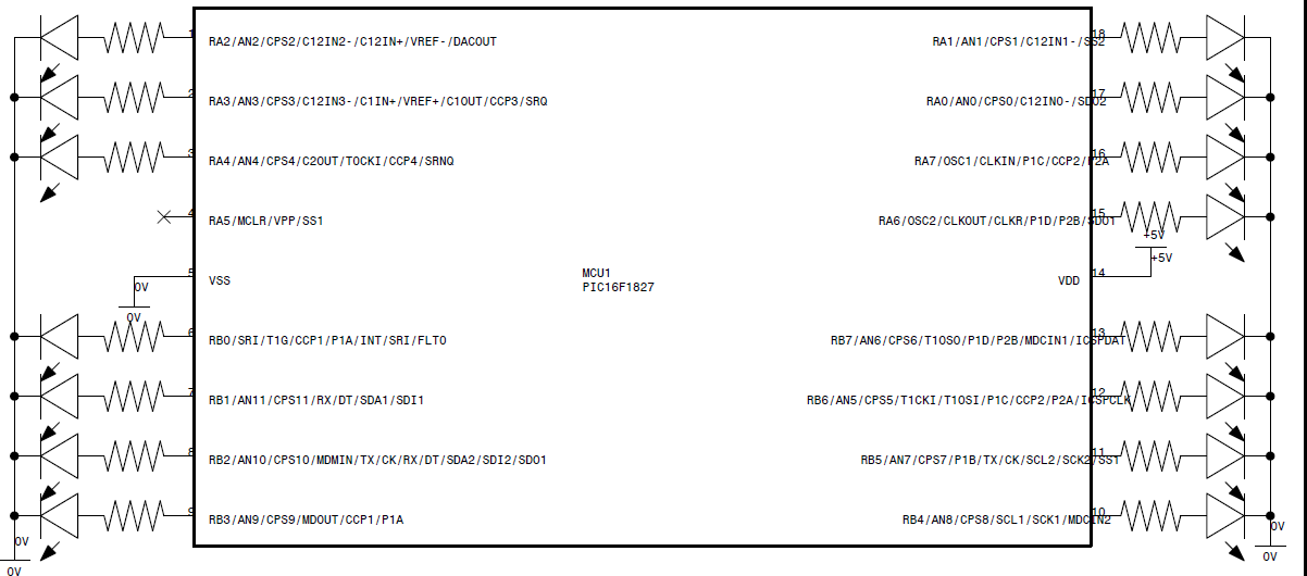
Here's the schematic for the cascading lights circuit. As you can see it's just one MCU and LEDs on all the pins except for pin#4 (RA5) which is an input-only pin. Resistors can be as low as, oh about, 180 ohms for a power supply of 5 volts. You have to watch out for the maximum rating of each pin (25mA if I remember correctly) and the maximum for each PORT.
----
Schematic when using a PIC16F84A

im a new to electronics.. but i can solder and know about polarities, can u give me a detailed schematic of this snowfall led.. i wanna do it my self.. u can mail me at my facebook account.. luther valiente, i provided my facebook url below.. thanks! and nice work!
ReplyDeleteHello Luther. The circuit is very simple. It uses one Microchip PIC 16F1827 microcontroller, 15 LEDs and 15 resistors. And a power supply.
ReplyDeleteThe magic that makes the snowfall effect is in the software. If you're new to electronics you'll need to learn how to program microcontrollers and to have a programmer (such as the PICkit 2 or PICkit3) to build this circuit. The software (also called firmware) that drives the micrcontroller is the long code I posted above. You'll also need the mikroC compiler if you're going to use the above code. It's free for download at the http://www.mikroe.com/eng/products/view/7/mikroc-pro-for-pic/
Let me draw the schematic and I'll add it to this blog entry.
Welcome to the fascinating world of electronics :)
thanks for the reply edwardson.. i wonder if i can use other MCU like pic16f8.. somthin like that cuz i cant find ang pic16f1 here.. by the way im from philippines.. can i still use the same code for that particular Pic like the pic16f8... and how can i remove the twinkle effect? cuz i just want it snowfall lol... if its ok with u, add me on facebook my url is http://www.facebook.com/profile.php?id=100000569713796 thanks again bro!
ReplyDeleteHi again. Yes you can use other PICs as well. But the "LATA" and "LATC" will have to be changed to "PORTA" and "PORTC" (or PORTB if it doesn't have a PORTC). The "ordinary" mid-range PICs don't support the LATx register. Only the enhanced midrange PIC12F1xxx/PIC16F1xxx does and the high performance PIC18. Also, it would be to wise to check the OSCCON register to make sure the bits are set up correctly for the PIC you're going to use. To simplify matters use a PIC that has an internal oscillator. The (formerly) popular PIC16F84 does not have this internal oscillator and so you'll have to put in a crystal or resistor-capacitor pair.
ReplyDeleteThe twinkle effect can easily be turned off by commenting out or deleting the following lines in "void main()"
DelayDsec(twinkle_delay);
Twinkle()
Finally, the kind of LED you're using matters a lot. Using ordinary LEDs only allows for a very narrow angle at which the light can be seen. Commercially available cascading lights use LEDs that that have a very wide spread and so the light is visible from practically any angle.
Hope that helps.
oh my brain is blank at the moment :( lol.. the available PIC here is PIC16F84A.. im really new to this but im willing to learn.. can i use PIC16F84A? and can u do the program code in mikroC for PIC16F84A? a schematic for that PIC will be a great help to.. i dont know wer to put the crystal or the resistor ur talking about and the value.. i will be also using a DIY programmer using the serial port and not the usb, i dont have the Pickit 2 and i think it would be costing me much.. hope u can help me out bro! thanks again!
ReplyDeleteWell if the 16F84A is what you have at the moment then it'll do. Download the datasheet. http://ww1.microchip.com/downloads/en/devicedoc/35007b.pdf You'll need to refer to the datasheet whenever working with microcontrollers. Go to page 23 and look at the Fig. 6-3. It provides the schematic as well as the recommended values for the resistor and capacitor. If you want to use a crystal check out Fig. 6-1.
ReplyDeleteBecause it doesn't have an internal oscillator, the number of pins for output is limited to 13. So that's 13 LEDs instead of 15.
The 84A doesn't have PORTC so you'll be using PORTA and PORTB. It also doesn't have an OSCCON register so delete or comment it out in the "void IniReg()" function. You'll also have to make sure to set the configuration word properly. If you're going to use mikroC that'll be easy. That compiler has a menu that allows changing the values.
There's one minor problem. The 84A has only one timer. In the program I use two timers-- timer 0 and timer 1. The 84A only has timer 0. Timer 1 is used only for the function void DelayDsec(int8 dsec), so you can just comment out or delete the function call "DelayDsec(cascade_delay);" in void main().
Take your time learning. Getting firmware to work can not infrequently be frustrating but it's all part of the game.
I just remembered that some of these older PICs have what's known as "open drain" pins. They're analogous to an open (bipolar transistor) collector. Simply means these pins can only sink current, they cannot source current. And sure enough the 84A has one open drain pin-- RA4 which is pin#3. The only way to use this pin is to reverse the anode and cathode of the LED so that current flows into the pin. I'll upload a schematic shortly. The firmware code doesn't need to be changed (except for those items which I already mentioned).
ReplyDeletewell thanks for the help bro! i know its hard for me to absorb all this quick.. ill try to do everything u told me, and hope i can make this work.. im also watching ur youtube videos, wish u can upload a tutorial on how to do it with the 84A PIC. ill keep u updated if i ever have a problem with this.. thanks!
ReplyDeleteSimulated this in Proteus..
ReplyDeleteWatch here:
http://www.youtube.com/watch?v=QQ3eL4d2c7A
I wonder why LED12 is always "ON"?
Hi
ReplyDeletecan i use 16f628a instead of PIC16F1827 and 16F84A? Should i change anything or not?
I have no experience in electronics...
Thank you in advance
Dagg
Hello Dagg. For the 16F628A use the schematic for the 16F84A. That's because the 628 also has an open drain output on RA4. And change all occurences of LATA and LATB to PORTA and PORTB respectively. Delete or comment out the following statements
ReplyDeleteOSCCON = 0b1110000;
ANSELA = 0;
ANSELB = 0;
or you'll get an error at compilation time (because those special registers don't exist in the 628).
Because the 628A has a max internal clock frequency of 4Mhz change the following:
#define t0_ini 256-128
#define t1h_ini 256-98
to
#define t0_ini 0
#define t1h_ini 256-196
You'll have to enable the internal clock via the configuration bits. Do this in mikroC.
You'll also have to disable the voltage comparators which are on by default by including the following C statement:
CMCON = 0b111;
Put that statement in the IniReg() function, right before the TRISx statements.
Hopefully that's all the changes that need to be made. If I think of anything else I'll post them.
Thank you for your help.
ReplyDeleteShall i have the same effect using 16F628A or not?
Dagg.
Yes, you should get the same effect.
ReplyDeleteOoops! Just noticed I made a mistake. I increased instead of decrease the timer ticks.
ReplyDeleteThat should be
#define t0_ini 256 - 64
#define t1h_ini 256 - 49
Those are for the timers. Since the 628 will be running at half the speed of the 1827, we have to decrease the "tick" of the timer 0 and timer 1.
Hi, I'm trying to put your program to PIC16F628A and can not compile it to me, have consulted, thank Mapi
ReplyDeletehttp://mapi-snowfallledlight.blogspot.com/
Hello mapi. There are coding errors. In your defines you wrote "PORTA.0". That should be "PORTA.f0" The "f" is necessary. Change all the PORTA.x to PORTA.fx. Same goes for PORTB.x
ReplyDeleteI haven't checked the rest of the code.
Hello Edwardson. Thank you for the correction and beautiful Christmas wish.
ReplyDeleteYou're welcome MaPi. Enjoy the holidays.
ReplyDeletehttp://pihrt.com/index.php/elektronika/49-info/203-vanocni-osvetleni-led-krapnik-s-efektem-snezeni
ReplyDeletewhat are the resister values and capacitor values
ReplyDeleteHello Niluka. If you're referring to the resistor and capacitor values for the oscillator of the 16F84A, please check the datasheet.
ReplyDeleteawesome post, bro..
ReplyDeleteHi,
ReplyDeleteI build this using PIC16F628. It works properly but after one turn of the LEDs, has a long delay before next turn. How can I reduce this. I want continuous flowing.
Kalinga
Hi, thanks a good program, but if it is possible to rewrite the basic language > Pic Basic Pro Compiler. Please send to my email .thanks. r_salimi20@yahoo.com
ReplyDeleteHello Mr. Edwardson , after realizing his project with pic 16F84A I find excellent , I wanted to ask if I wanted to change it with the effect supecar with the trail " effect lights back and forth which changes could I do? Can help me please?
ReplyDeletethank you
Welcome to Jainsons Lights for Buy Crystal Chandeliers Online at an affordable price. We are famous as a number one lighting, ceiling fan, and chandelier retailer. Your unique Lighting experience begins the instant you enter our front entrance. With our extensive range, you’ll be spoilt for choice, while our renowned customer service will make sure the entire process is enjoyable and inspirational.
ReplyDeleteLooking for reliable Waterproof LED Lights in Delhi? Prakriti Global offers high-quality and energy-efficient LED lighting designed for outdoor durability. Their waterproof LED lights are ideal for gardens, pathways, building exteriors, landscapes, and architectural lighting projects.To explore their range of waterproof LED lighting products or to get expert guidance, visit their website: https://prakritiglobal.in/
ReplyDeleteor contact their team directly at +91 8851070527 for more information.
Elevating strategic thinking with trusted perspectives for those leading change.
ReplyDeleteEnrgtech Distributor