PCB artwork for the main board and the LED boards. Main board is 3 x 5". The three LED boards are all 1.25 x 1.5".


Freshly etched boards. I made an extra of what I call the "platform"--the board onto which the two 7-segment LED boards named ALPHA and BETA are soldered to at right angles.


Below is the panel broken into four boards using the score and snap method. These have already been drilled (except for the extra board).

A 9-pin connector runs from the main board to the platform board. I soldered two cables back-to-back. You can see the white female plugs at the top and bottom of the photo. The other bundle of wires is the original cable for the bulbs.


That round yellow thing is a rubber pad inserted so that the signal tower and the plastic box are not rigidly connected to one another. From the looks of it the box is made of (high impact) polystyrene and is brittle. Sharp knocks and blows will crack it. The rubber acts to partly absorb shocks and prevent breakage. The three screws are tightened only to the point that the rubber is compressed a little bit.

The biggest headache for me was finding a way to mount the LED display on top of the signal tower. Fortunately I found this plastic pill and trinket storage set. The individual canisters screw on top of one another with a final screw-on cap on top. Its diameter is 50mm--exactly the same as the signal tower's. I took the cap and one of the canisters and drilled the appropriate holes. I don't have a coping saw or router so I just used the drill bit to cut out the shapes for the connectors. Messy and crude but it worked.


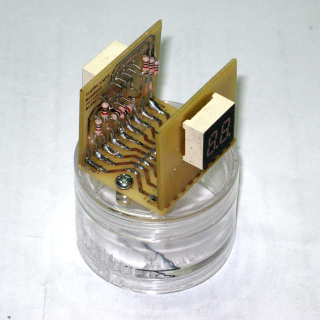
The countdown timer installed on top of the tower. I discarded the original (beige) cap of the signal tower and screwed in the canister instead.


The main board before and after the various wires were connected. You will notice the chopstick extension piece glued to the yellow push button. As in the previous model that stick pokes through a hole on top half of the plastic box. The board is secured to the base of the box using hot melt glue.


Here's a vid showing how the traffic light works.
As I mentioned above I've made some revisions to the drafts of the schematic and firmware. Here are the final versions.


MCU = Microchip PIC16F1827 microcontroller
D1 = 1N5822 Schottky diode
VR = 78L05 +5V voltage regulator
7SEG1, 7SEG2 = 306IDB common anode 2-digit 7-segment LED
Q1, Q2, Q3 = TIP102 NPN Darlington transistors
Q4, Q5 = S9012 PNP transistors
Q6, Q7 = 2N7000 MOSFET transistors
Q8 = ULN2003 transistor array
LR, LR, LG = incandescent lamps
/*

Kids' Traffic Light with Countdown Timer Using an Industrial Signal Tower

Created:        January 2012
Processor:      PIC 16F1827
Compiler        mikroC Pro 5.0.0
Remarks:        see "kids traffic light.dwg" for schematic
Configuration:  power up timer, brownout reset (set to 2.5V), WDT, stack over/underflow reset -- all enabled, all others disabled

* Uses a 12VDC wall wart as power supply

* Tower light 12VDC red, amber, green incandescent lamps are switched by NPN Darlington transistors

* pushbutton:
     * when momentarily pressed: cycles through different possible modes:
          1. flashing amber
          2. flashing red
          3. alternating amber and red
          4. normal traffic light: green -> amber -> red

     * when pressed and kept depressed for over a couple of seconds LED display shows 1,2,3,4,5,6 in sequence corresponding to following go/stop on-time:
          1. 5sec
          2. 10sec
          3. 15sec
          4. 20sec
          5. 25sec
          6. 30sec
     * although LED readout can be made to show number of real-time seconds when selecting go/stop time
       showing it in the manner above provides an opportunity to teach the children how to multiply--in this case multiply by 5

* go/stop on-time is stored in EEPROM

* has 7-segment LED display
     * shows the go/stop on-time when selecting it
     * shows the remaining time before light changes
     * shows various non-numeric characters in other modes


*/


// ************************************************************************************************
//       input / output
// ************************************************************************************************

#define  lred                LATB.f3             // NPN darlington switches 12VDC incandescent lamp
#define  lamber              LATB.f2             // NPN darlington switches 12VDC incandescent lamp
#define  lgreen              LATB.f1             // NPN darlington switches 12VDC incandescent lamp

#define  pb                  PORTB.f6            // momentary contact push button
#define  tris_pb             TRISB.f6            // for setting pb pin as input
#define  wpu_pb              WPUB.f6             // for enabling weak pullup

#define  anode_ones          LATB.f5             // S9012 PNP transistor
#define  anode_tens          LATB.f4             // S9012 PNP transistor

#define  seg_a               LATA.f4             // segment a of seven segment LED common anode
#define  seg_b               LATA.f3             // segment b of seven segment LED common anode
#define  seg_c               LATA.f0             // segment c of seven segment LED common anode
#define  seg_d               LATA.f6             // segment d of seven segment LED common anode
#define  seg_e               LATA.f7             // segment e of seven segment LED common anode
#define  seg_f               LATA.f1             // segment f of seven segment LED common anode
#define  seg_g               LATA.f2             // segment g of seven segment LED common anode

// ************************************************************************************************
//       traffic light time duration
// ************************************************************************************************

#define  count_ini           250       // number of timer2 ticks to make one second

#define  ambertime           500       // in normal mode -- amount of time for amber light to be on after green and before red -- time in terms of timer2 ticks
#define  flashambertime      200       // in flashing amber mode -- amount of time for amber light to be on and amount of time to be off -- time in terms of timer2 ticks
#define  flashredtime        200       // in flashing red mode -- amount of time for red light to be on and amount of time to be off -- time in terms of timer2 ticks
#define  flashredambtime     200       // in red/amber alternate flashing mode -- amount of time for red light to be on and amount of time amber light to be on -- time in terms of timer2 ticks
#define  ledflashtime        25        // in normal mode during yield (amber light) -- amount of time the character displayed on 7-seg is flashed on and off

#define  changergtime        375       // minimum amount of time for button to be kept pressed before cycling through the green light on time -- time in terms of timer2 ticks
                                       // given 4ms timer2 tick, changergtime of 250 = 1sec real time

#define  prechangergtime     changergtime - 250  // amount of time after button is held down when all lights are turned off in preparation for possible change of green/red light on time

#define  rgtime_increm       1250      // amount of time for green/red light to be on, and multiples thereof upon continual button press -- value in terms of timer2 ticks.
#define  maxrgtime           6         // maximum allowed multiple of rgtime_increm

int16 REDGREENTIME;                    // amount of time for green/red light to be on -- time in terms of timer2 ticks
int8  RGTIME;                          // multiples of rgtime_increm such that RGTIME*rgtime_increm = REDGREENTIME


// ************************************************************************************************
//       for pushbutton
// ************************************************************************************************

#define  rising              1         // rising edge detected. used by PBedge
#define  released            1         // rising edge detected. used by PBedge
#define  falling             2         // falling edge detected. used by PBedge
#define  pressed             2         // falling edge detected. used by PBedge
#define  none                0         // no edge. used by PBedge

int8 PBval;                            // last eight values of the switch upon reading it
int8 PBedge;                           // edge detected?, 0 = no edge detect, 1 = rising edge, 2 = falling edge; other values = Not Used / Undefined for now
bit PBlevel;                           // voltage level of switch when not bouncing (hi = 1, lo = 0)

// ************************************************************************************************
//       general defines and variables
// ************************************************************************************************

#define  int1                bit
#define  int8                unsigned char
#define  int16               unsigned int
#define  int32               unsigned long

#define  on                  1
#define  off                 0

#define  input               1         // for TRISx
#define  output              0         // for TRISx

#define  analog              1         // for ANSELx
#define  digital             0         // for ANSELx

#define  addr_rgtime         0x10      // eeprom address for user selected green/red light on time

#define  disp_dash           111       // code to display a dash, for use with UpdateDisp()

#define  disp_3horiz         120       // code to display three horizontal segments, for use with UpdateDisp()
#define  disp_tophoriz       121       // code to display top horizontal segment, for use with SegmentAssign()
#define  disp_midhoriz       122       // code to display middle horizontal segment, for use with SegmentAssign()
#define  disp_botthoriz      123       // code to display bottom horizontal segment, for use with SegmentAssign()

#define  disp_brackets       130       // code to display brackets, for use with UpdateDisp()
#define  disp_left_bracket   131       // code to display left bracket, for use with SegmentAssign()
#define  disp_right_bracket  132       // code to display right bracket, for use with SegmentAssign()

#define  disp_topsquare      141       // code to display top square, for use with UpdateDisp()
#define  disp_bottsquare     142       // code to display bottom square, for use with UpdateDisp()

#define  disp_blank          255       // code to display nothing, for use with UpdateDisp()

int16 TIME = 0;                        // records how long a light has been on  -- in terms of timer2 ticks
int8  VALUE = disp_blank;              // number or character to be displayed on 7-seg LED
int8  RGSECONDS;                       // user-selected red/green on-time in real-time seconds


// ************************************************************************************************
//       for state machines
// ************************************************************************************************

// !! A C H T U N G !!
// make sure all non user selectable modes such as _standby and _selectrgtime come AFTER user selectable
// and that _normal" is the last item in the valid user selectable modes because it is used as the max value in ProcessKey()
enum {_flashingamber, _flashingred, _flashingredamber, _normal,
      /* the modes that follow are non-user selectable --> */ _standby, _selectrgtime} STATEMODE = _flashingamber;

enum {_stop, _yield_ini, _yield, _go} STATENORMAL = _stop;
enum {_init, _flash} STATEFLASHGREEN = _init;


// ===========================================================================================
//       LED 7-Segment Display
// ===========================================================================================

void SegmentAssign(int8 num)
{
  seg_a = 0;
  seg_b = 0;
  seg_c = 0;
  seg_d = 0;
  seg_e = 0;
  seg_f = 0;
  seg_g = 0;

  switch (num)
  {
    case 1:
      seg_b = 1;
      seg_c = 1;
      break;

    case 2:
      seg_a = 1;
      seg_b = 1;
      seg_d = 1;
      seg_e = 1;
      seg_g = 1;
      break;

    case 3:
      seg_a = 1;
      seg_b = 1;
      seg_c = 1;
      seg_d = 1;
      seg_g = 1;
      break;

    case 4:
      seg_b = 1;
      seg_c = 1;
      seg_f = 1;
      seg_g = 1;
      break;

    case 5:
      seg_a = 1;
      seg_c = 1;
      seg_d = 1;
      seg_f = 1;
      seg_g = 1;
      break;

    case 6:
      seg_a = 1;
      seg_c = 1;
      seg_d = 1;
      seg_e = 1;
      seg_f = 1;
      seg_g = 1;
      break;

    case 7:
      seg_a = 1;
      seg_b = 1;
      seg_c = 1;
      break;

    case 8:
      seg_a = 1;
      seg_b = 1;
      seg_c = 1;
      seg_d = 1;
      seg_e = 1;
      seg_f = 1;
      seg_g = 1;
      break;

    case 9:
      seg_a = 1;
      seg_b = 1;
      seg_c = 1;
      seg_d = 1;
      seg_f = 1;
      seg_g = 1;
      break;

    case 0:
      seg_a = 1;
      seg_b = 1;
      seg_c = 1;
      seg_d = 1;
      seg_e = 1;
      seg_f = 1;
      break;

    case disp_dash:          // displays a dash - middle horizontal segment
      seg_g = 1;
      break;

    case disp_3horiz:        // displays three horizontal segments
      seg_a = 1;
      seg_d = 1;
      seg_g = 1;
      break;

    case disp_tophoriz:      // displays top horizontal segment
      seg_a = 1;
      break;

    case disp_botthoriz:     // displays bottom horizontal segment
      seg_d = 1;
      break;

    case disp_left_bracket:  // displays opening bracket
      seg_a = 1;
      seg_d = 1;
      seg_e = 1;
      seg_f = 1;
      break;

    case disp_right_bracket: // displays closing bracket
      seg_a = 1;
      seg_b = 1;
      seg_c = 1;
      seg_d = 1;
      break;

    case disp_topsquare:     // displays a square on upper half of LED
      seg_a = 1;
      seg_b = 1;
      seg_f = 1;
      seg_g = 1;
      break;

    case disp_bottsquare:    // displays a square on the lower half of the LED
      seg_c = 1;
      seg_d = 1;
      seg_e = 1;
      seg_g = 1;
      break;

    default:                 // if invalid value then display blank

    case disp_blank:         // segments have already been turned off at the start of this function so do nothing
      break;
  } // switch (num)
} // void SegmentAssign(int8 num)


void UpdateDisp()
{
  static bit anode;          // flag bit multiplexing display between tens and ones place
  int8 TENS, ONES;           // contains the digit or code of the non-numeric character to be displayed in the tens and ones place

  // turn off power to 7-segment LED display.
  anode_ones = off;
  anode_tens = off;

  if (STATEMODE != _standby)         // turn on LED display only when not in _standby mode
  {
    if (VALUE < 100)                 // values >= 100 are codes for non-numeric characters
    {
      TENS = VALUE/10;
      ONES = VALUE%10;
    } // if (VALUE < 100)
    else
    {
      switch (VALUE)
      {
        case disp_dash:
          TENS = disp_dash;
          ONES = disp_dash;
          break;

        case disp_3horiz:
          TENS = disp_3horiz;
          ONES = disp_3horiz;
          break;

        case disp_tophoriz:
          TENS = disp_tophoriz;
          ONES = disp_tophoriz;
          break;

        case disp_botthoriz:
          TENS = disp_botthoriz;
          ONES = disp_botthoriz;
          break;

        case disp_brackets:
          TENS = disp_left_bracket;
          ONES = disp_right_bracket;
          break;

        case disp_topsquare:
          TENS = disp_topsquare;
          ONES = disp_topsquare;
          break;

        case disp_bottsquare:
          TENS = disp_bottsquare;
          ONES = disp_bottsquare;
          break;

        default:                       // if invalid value then display blank

        case disp_blank:
          TENS = disp_blank;
          ONES = disp_blank;
          break;
      } // switch (VALUE)
    } // else if (VALUE >= 100)

    if (anode)
    {
      if (TENS != 0)                   // do not display tens place if it's zero
      {
        SegmentAssign(TENS);
        anode_tens = on;
      }
      anode = 0;
    }
    else
    {
      SegmentAssign(ONES);
      anode_ones = on;
      anode = 1;
    }
  } // if (display)
} // void UpdateDisp()


// ===========================================================================================
//       functions
// ===========================================================================================

void ComputeRedGreenTime()
{
  REDGREENTIME = RGTIME*rgtime_increm;
  RGSECONDS = RGTIME*5;
}

void AllLightsOff()
{
  lred = off;
  lamber = off;
  lgreen = off;
}

void IniReg()
{
  // set internal clock frequency to 2MHz
  OSCCON = 0b1100000;

  TRISA = output;
  TRISB = output;
  ANSELA = digital;
  ANSELB = digital;

  tris_pb = input;

  // enable weak pull up for pushbutton
  OPTION_REG.NOT_WPUEN = 0;
  wpu_pb = 1;

  AllLightsOff();            // necessary to make sure incandescent lamps which should be off upon start up are off

  // Timer2 is used for state machine and switch debouncing timing tick
  // with clock = 2MHz, PR2 = 125, prescale = 1:16, postscale = 1:1
  // TMR2 will count from zero to PR2 and timer2 interrupt occurs every 125*16 / (2MHz / 4) = 4ms = timer2 tick
  T2CON = 0b110;             // postscaler = 1:1, prescaler = 1:16, timer2 on
  TMR2 = 0;
  PR2 = 125;

  WDTCON = 0b1000;           // prescale = 1:512 (16ms typical)
                             // WDTE in configuration word is configured so that WDT enabled when MCU awake and disabled when MCU asleep

  // retrieve stored green/red light on time value.
  // If eeprom-stored value is out of valid range then set it to minimum and store this value in eeprom
  // stored values are in terms of multiples of rgtime_increm such that stored value multiplied by rgtime_increm = time in terms of TMR2 ticks
  RGTIME = EEPROM_Read(addr_rgtime);
  if (RGTIME == 0 || RGTIME > maxrgtime)
  {
    RGTIME = 1;
    EEPROM_Write(addr_rgtime, RGTIME);
  }
  ComputeRedGreenTime();                     // REDGREENTIME = RGTIME*rgtime_increm;

  // initialize push button
  PBval = 0xFF;
  PBlevel = hi;
} // void InitRegisters()


// amber flashes on and off at a rate determined by flashambertime
// LED display shows the character stored in VALUE
void FlashingAmber()
{
  static bit flag;

  if (++TIME < flashambertime)
  {
    if (flag)
    {
      lamber = on;
      VALUE = disp_brackets;
    }
    else
    {
      lamber = off;
      VALUE = disp_blank;
    }
  }
  else
  {
    if (flag)
      flag = 0;
    else
      flag = 1;
    TIME = 0;
  }
} // void FlashingAmber()


// red flashes on and off at a rate determined by flashredtime
// LED display shows the character stored in VALUE
void FlashingRed()
{
  static bit flag;

  if (++TIME < flashredtime)
  {
    if (flag)
    {
      lred = on;
      VALUE = disp_brackets;
    }
    else
    {
      lred = off;
      VALUE = disp_blank;
    }
  }
  else
  {
    if (flag)
      flag = 0;
    else
      flag = 1;
    TIME = 0;
  }
} // void FlashingRed()


// red and amber turn on alternately at a rate determined by flashredambertime
// LED display shows the character stored in VALUE
void FlashingRedAmber()
{
  static bit flag;

  if (++TIME < flashredambtime)
  {
    if (flag)
    {
      lamber = off;
      lred = on;
      VALUE = disp_topsquare;
    }
    else
    {
      lred = off;
      lamber = on;
      VALUE = disp_bottsquare;
    }
  }
  else
  {
    if (flag)
      flag = 0;
    else
      flag = 1;
    TIME = 0;
  }
} // void FlashingRedAmber()


// normal traffic light operation: green --> amber --> red
// red/green light on-time is user selectable
// LED display shows the countdown time in seconds during red and green light
// LED display shows a flashing "--" during amber light, blink rate determined by ledbflashtime
void Normal()
{
  static int8 COUNTER;
  static bit toggle;

  switch (STATENORMAL)
  {
    case _stop:
      if (++TIME < REDGREENTIME)
      {
        lred = on;
        if (--COUNTER == 0)
        {
          --VALUE;
          COUNTER = count_ini;
        }
      }
      else
      {
        STATENORMAL = _go;
        TIME = 0;
        COUNTER = count_ini;
        VALUE = RGSECONDS;
        lred = off;
      }
      break;

    case _yield_ini:
      toggle = 1;
      VALUE = disp_dash;
      COUNTER = ledflashtime;
      TIME = 0;
      STATENORMAL = _yield;
      break;

    case _yield:
      if (++TIME < ambertime)
      {
        lamber = on;

        if (--COUNTER == 0)
        {
          if (toggle)
          {
            VALUE = disp_blank;
            toggle = 0;
          }
          else
          {
            VALUE = disp_dash;
            toggle = 1;
          }
          COUNTER = ledflashtime;
        }
      }
      else
      {
        STATENORMAL = _stop;
        TIME = 0;
        COUNTER = count_ini;
        VALUE = RGSECONDS;
        lamber = off;
      }
      break;

    case _go:
      if (++TIME < REDGREENTIME)
      {
        lgreen = on;
        if (--COUNTER == 0)
        {
          --VALUE;
          COUNTER = count_ini;
        }
      }
      else
      {
        STATENORMAL = _yield_ini;
        lgreen = off;
      }
      break;

    default:
      TIME = 0;
      STATENORMAL = _yield;
  } // switch (STATENORMAL)
} // void StateMachNormal()


void StateMachMain()
{
  switch (STATEMODE)
  {
    case _normal:
      Normal();
      break;

    case _flashingamber:
      FlashingAmber();
      break;

    case _flashingred:
      FlashingRed();
      break;

    case _flashingredamber:
      FlashingRedAmber();
      break;

    case _standby:           // do nothing mode where all bulbs are off. used when changing red/green on-time
      break;

    case _selectrgtime:      // er uhhh, I guess we do nothing as well
      break;

    default:
      STATEMODE = _normal;
  }
} // void StateMachMain()


void DebounceSwitch()
{
  // shift all bits to the left
  // if switch reading is hi then let pb_val bit 0 = 1
  PBval <<= 1;
  if (pb)
    ++PBval;

  PBedge = none;

  // if level is lo and all bits of pb_val are now hi then
  // a rising edge has been detected
  // switch is considered just released when rising edge is detected
  // switch level is now hi
 if ((!PBlevel) && (PBval == 0xFF))
  {
    PBlevel = hi;
    PBedge = rising;
  }

  // if level is hi and all bits of pb_val are now low then
  // a falling edge has been detected
  // switch is considered just pressed when falling edge is detected
  // switch level is now lo
  if ((PBlevel) && (!PBval))
  {
    PBlevel = lo;
    PBedge = falling;
  }
} // void DebounceSwitch()


void ProcessKey()
{
  int8 MODE;                           // temporary storage of current STATEMODE

  static  int16  PBPRESSTIMETOTAL = 0; // Keeps track of how long PB is depressed in terms of timer2 ticks
                                       // Keeps track of total time from falling edge (switched pressed) to rising edge (switch released).
                                       // if less than changergtime then we know the keypress is momentary and user wants to change modes

  static  int16  PBPRESSTIME = 0;      // Keeps track of how long PB is depressed in terms of timer2 ticks
                                       // this variable is reset every time it exceeds changergtime
                                       // every time it exceeds changergtime red/green on-time is incremented until masrgtime and then it cycles back to one

  DebounceSwitch();
  MODE = STATEMODE;

  if (PBlevel == lo)
  {
    if (++PBPRESSTIMETOTAL == prechangergtime)
    {
      AllLightsOff();
      STATEMODE = _standby;
    }

    if (++PBPRESSTIME >= changergtime)
    {
      PBPRESSTIME = 0;
      if (++RGTIME > maxrgtime)
        RGTIME = 1;
//      EEPROM_Write(addr_rgtime, RGTIME);
//      ComputeRedGreenTime();                     // REDGREENTIME = RGTIME*rgtime_increm;
      STATEMODE = _selectrgtime;
      VALUE = RGTIME;                            // RGTIME will be displayed on the LED readout
    } // if (++PBPRESSTIME >= changergtime)
  } // if (PBlevel == lo)

  if (PBedge == released)
  {
    if (PBPRESSTIMETOTAL < changergtime)         // if pushbutton was only momentarily pressed then change to the next mode
    {
      STATEMODE = ++MODE;
      if (STATEMODE == _normal)
        STATENORMAL = _yield_ini;                // this is necessary to start normal traffic light mode properly
      else if (STATEMODE > _normal)
        STATEMODE = 0;
    } // if (PBPRESSTIMETOTAL < changergtime)
    else  // green/red light on time has been changed so go to normal traffic light mode and begin with amber light
    {
      EEPROM_Write(addr_rgtime, RGTIME);
      ComputeRedGreenTime();                     // REDGREENTIME = RGTIME*rgtime_increm;
      STATEMODE = _normal;
      STATENORMAL = _yield_ini;
    }

    AllLightsOff();          // turn off all bulbs and let state machine take care of which ones to turn on
    TIME = 0;                // reset timer so that whatever mode has been selected, light will go through full time allotted
    PBPRESSTIMETOTAL = 0;
    PBPRESSTIME = 0;
  } // if (PBedge == released)
} // void ProcessKey()


void main()
{
  IniReg();

  while(1)
  {
    if (PIR1.TMR2IF)
    {
      PIR1.TMR2IF = 0;
      asm{clrwdt}
      UpdateDisp();
      ProcessKey();
      StateMachMain();
    } // if (PIR1.TMR2IF)
  } // while(1)
} // void main()
No comments:
Post a Comment