My sister's family and I spent the afternoon together last Sunday. Had a late lunch at a fine dining restaurant. Food was great. Unfortunately the kids still need years to develop a taste for good food. Their dad said he'd just bring them to Krispy Kreme after lunch to fill their bellies.
At least twice during the meal the 5- and 4- year old had to go to the washroom. Being the good and lovable uncle I accompanied them.Well, it proved to be an adventure for the boys. The urinals in the air conditioned and plush restrooms had infrared sensors to detect the presence of, well, humans. As can be expected the brats had a ball playing with them, tripping them off with their hands and watching as the gizmo flushed water down.
That evening it occurred to me that I could easily design a circuit the kids can have fun with to turn on a light or just an LED. I already have a circuit installed in my home that switches on the ceiling lights whenever I cross the hallway. It's a windowless area and is pitch black at night. With the circuit I don't have to go back and switch off the lights. The sensor is a Keyence PZ-51 infrared transmitter-receiver with an NPN output, which I set up as a reflective system with the emitter and detector side by side. When something/someone reflects enough of the infrared beam back to the receiver the circuit gets triggered and the lights are switched on for a little over half a minute. A 3-second beep sounds right before the lights go out to warn the person.
Given my experience with photoelectric sensors and the fact that I still have a number of these Keyence products I got from a sale almost a decade ago, I started designing a circuit based on photosensors. But I hadn't even drawn a single schematic when it hit me that this was just overkill. Using an industrial part like the Keyence didn't seem right. Worse, it isn't kid-proof at all!
I needed something simpler and more rugged, something more or less immune to the bashing, smashing, "crayoning," drooling, and what-have-you the sensor will be up against and subjected to with a brood of 2-, 3-, 4-, and 5-year olds. So it occurred to me--Why not detect the 60Hz hum that everyone in the city conducts? That way the sensor could be any conductor--a length of wire, small thumb-sized metal sheet, maybe even the door handle of a cabinet.
Mulling over the circuit requirements, it seemed to me that what had to be done was to amplify the signal from the human touch and pass it through a comparator with hysteresis to get a good clean digital output. I hit the breadboard and configured one of the op amps of a MCP6232 dual op amp as a noninverting amplifier with a gain of 100 and the other as a comparator. Well, surprisingly, it worked!
Oscilloscope showed, however, that there was a lot of high frequency noise being amplified as well. So I figured I'd add a low pass filter (LPF) at the front end (before the amplifier) with a cutoff frequency (Fc) of around 120Hz .To try it out I used a good round figure of 100Kohm and 10nF which gave an Fc of 160Hz.(equation is 1/(2πRC)). Sure enough it cleaned up the signal pretty well.
The design was practically finished and I could feed the 60Hz pulse train output of the comparator to a microcontroller and have that MCU process the signal and turn on lights and buzzers, etc. for, say, a specified amount of time. It can even reject rapid multiple "button presses" to prevent the light from being turned too many times a minute. Or it can process such multiple contacts as a code to turn the load on for a certain amount of time or certain fashion, etc. Once the analog end was able to provide a reliable signal, the MCU could do the rest. And if the MCU had an onboard comparator then we need only filter and gain the input signal before sending it to the MCU.
But I wasn't satisfied. I wanted to push myself and create an output (from the op amps) that stayed high (Vcc) the moment the comparator was triggered and then drop out (go to ground) once the 60Hz pulse train ceased. In other words, if I hooked up the output to trigger an NPN, the transistor would be completely and continuously on while the user was touching the sensor.
So what I had to do was to convert that pulse train from the comparator to a DC signal that would rise to and remain above a certain minimum voltage while the user was touching the sensor. My solution? An LPF with a Fc of <60Hz.
As a first cut, I used a 1uF tantalum and 100Kohm to give an Fc of 1.6Hz. I then got another MCP6232 and configured one of the op amps as a noninverting comparator (with no hysteresis). The output of the passive LPF was then fed directly into the noninverting input of the op amp.
Lo and behold! I got what I wanted. Well, almost. Not surprisingly the long RC constant of the 1.6Hz LPF caused a hell of a delay in the response of the second comparator. After the user touches the sensor it took tens of milliseconds for the voltage to ramp up to the trip point of the comparator and then after the sensor ceased detecting contact, it took about a hundred milliseconds for the voltage to decay below the trip point. Very slow and humanly noticeable delay.
To alleviate this, I had to decrease the RC constant which meant increasing the Fc. I chose 6Hz. Oscilloscope showed a very significant increase in ripple voltage. And this of course meant that the comparator (remember, it had no hysteresis) could rapidly go high and then low and then high again as the voltage was passing the comparator trip point. And in fact, tests showed that this does happen every once in a while. This meant that hysteresis had to be designed into the circuit.
Which I did. I added positive feedback using two resistors. When I tried the circuit it was a dud. Why? Because the output of the passive LPF is high impedance. The noninverting input of the comparator is very high impedance but with the positive feedback resistors also connected to the noninverting pins of the op amp that just changes the circuit characteristics. Solution was simple but required the use of another op amp. The LPF had to be buffered by a voltage follower (unity gain amplifier). This low impedance signal could then be fed to the comparator with hysteresis.
 The following is the final circuit (for now) after tweaking the values for the LPFs, hysteresis, comparator voltage reference, etc. Load resistor RL is necessary and has to be high value. The lower the value the more attenuated the signal becomes. I used a 3Meg in the test circuit. The front end LPF has a Fc of 72Hz. You might notice the "coax." in the schematic. A coaxial cable is needed only if the sensor--a fingernail-sized touch plate for instance--will be located more than a few centimeters from the circuit board. Any plain old conductor acts as an antenna picking up the 60Hz hum; and the longer the conductor the higher the amplitude of the signal. At the amplifier gain of 100, a wire longer than 20 centimeters will transmit a large enough signal to trigger the first comparator. I've actually tried using a meter-long coaxial wire and it does work--the circuit is not triggered unless the far end of the coax is touched. The copper braid (shield) of the coax must be electrically connected to circuit ground.
Note that amplifier A3 is no longer a voltage follower that buffers the 6Hz LPF, but a noninverting amplifier with a gain of 2. The reason is that the buffered LPF signal was approx 2.3VDC with a ripple voltage of around 850mV peak to peak. The upper threshold trip voltage of the comparator A4 is about 1.8VDC. This is no problem when the sensor is fully touched--that is, output of A1 reaches the positive rail (and you get a quasi rectangular pulse train, not a half sine wave). But when A1output is weak (low amplitude but is above the upper threshold trip voltage of comparator A2) the duty cycle of the output of A2 drops and so there is much less on time for CF2 to charge, resulting in a much lower average DC of the LPF output. This causes comparator A4 to fail to trigger. Thus, it was necessary to gain the LPF output to make sure that when A2 trips, A4 will trip too. Both comparators are referenced to 30% Vcc.
Finding the equations for determining the upper and lower threshold voltages of the comparators has been a headache. Still is. The commonly given equations in textbooks are for op amps/comparators using a bipolar power supply. I'm using a single supply. I did find single supply equations in the datasheet for the MCP6541 comparator. However, measurements using an oscilloscope (see below) do not tally with the results from the equations. Perhaps input signals to comparators A2 and A4 need to be buffered.
What follows are oscilloscope (Rigol 1102E) screenshots of the circuit in action. Refer to the schematic for test points P1 to P4.

Test point: P1
Output of A1 when sensor (a 14-cm AWG 22 wire) has not been touched. As can be seen the measured frequency is 60.2Hz and Vpp = 720mV

Test point: P1
Output of A1 when sensor touched. The amplifier saturates. (The Vpp as measured by the scope can't be right of course given the 1.00V/div)

Ch1 test point: P2
Ch2 test point: P1
Ch1: 2.00V/div
Ch2: 1.00V/div
Trigger: Auto, Ch2, 200mV, rising edge
Sensor touched. The output of comparator A2 is almost a square wave. The output of A1 is coming close to square wave. (The scope's Vpp measurement of A1 output is now correct)

Ch1 test point: P2
Ch2 test point: P1
Ch1: 2.00V/div
Ch2: 1.00V/div
Trigger: Auto, Ch2, 200mV, rising edge
Sensor not touched.

Ch1 test point: P3
Ch2 test point: P1
Ch1: 2.00V/div
Ch2: 1.00V/div
Trigger: Auto, Ch2, 200mV, rising edge
Sensor is touched. In the above screenshot output of A3 has already stabilized. With the gain of 2 the LPF output reaches positive rail.

Ch1 test point: P3
Ch2 test point: P2
Ch1: 2.00V/div
Ch2: 1.00V/div
Trigger: Auto, Ch2, 200mV, rising edge
Sensor is touched.

Ch1 test point: P2
Ch2 test point: P1
Ch1: 2.00V/div
Ch2: 1.00V/div
Time base:10.0ms/div
Trigger: Single sweep, Ch1, 200mV, rising edge,
Here we see the very moment A1 output trips comparator A2

Ch1 test point: P2
Ch2 test point: P1
Ch1: 1.00V/div
Ch2: 1.00V/div
Time base: 500microsec/div
Trigger: Single sweep, Ch1, 200mV, rising edge,
This is a zoomed in portion of the preceding single sweep capture. Cursors have been turned on and manually adjusted to the point of intersection between the output of A1 and A2. The scope measures the hysteresis band at 840mV. Comparator A2 upper threshold voltage = 1.88V, lower threshold voltage = 1.04V

Ch1 test point: P3
Ch2 test point: P1
Ch1: 1.00V/div
Ch2: 1.00V/div
Time base: 20.0ms/div
Trigger: Single sweep, Ch1, 200mV, rising edge,
This clearly shows that because of the RC constant of the 6Hz LPF there will be a delay before A4 output goes high.

Ch1 test point:P4
Ch2 test point: P1
Ch1: 1.00V/div
Ch2: 1.00V/div
Time base: 20.0ms/div
Trigger: Single sweep, Ch1, 200mV, rising edge
The delay between touching the sensor and A4 output going high can be seen here. Also shows the clean digital output of A4. The ripple voltage is due to the power supply.

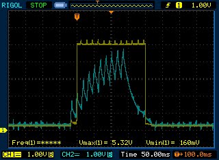
Ch1 test point: P3
Ch2 test point: P2
Ch1: 1.00V/div
Ch2: 1.00V/div
Time base: 50.0ms/div
Trigger: Single sweep, Ch2, 200mV, rising edge
Rise and decay of A3 output in relation to comparator A2 output

Ch1 test point: P3
Ch2 test point: P2
Ch1: 1.00V/div
Ch2: 1.00V/div
Time base: 20.0ms/div
Trigger: Single sweep, Ch2, 200mV, rising edge

Ch1 test point: P4
Ch2 test point: P2
Ch1: 2.00V/div
Ch2: 1.00V/div
Time base: 20.0ms/div
Trigger: Single sweep, Ch2, 200mV, rising edge
A4 output in relation to A2 output. What is most evident is the large delay in A4 output droput

Ch1 test point: P4
Ch2 test point: P2
Ch1: 2.00V/div
Ch2: 1.00V/div
Time base: 2.0ms/div
Trigger: Single sweep, rising edge, Ch2, 200mV
This is a zoomed in portion of the preceding capture. Cursors are on to measure the delay between comparator A2 output and A4 output. In this particular case it's 3.5ms

Ch1 test point: P4
Ch2 test point: P2
Ch1: 2.00V/div
Ch2: 1.00V/div
Time base: 2.0ms/div
Trigger: Single sweep, Ch2, 200mV, rising edge
This is a zoomed in portion of the second to the last capture. Cursors are on to measure the delay between comparator A2 dropout and A4 dropout. In this case it's 57ms.
Ch1 test point: P4
Ch2 test point: P3
Ch1: 1.00V/div
Ch2: 1.00V/div
Time base: 50.0ms/div
Trigger: Single sweep, rising edge, Ch1, 1.0V

Ch1 test point: P4
Ch2 test point: P3
Ch1: 1.00V/div
Ch2: 1.00V/div
Time base: 2.0ms/div
Trigger: Single sweep, Ch1, 1.0V, rising edge
This is a zoomed in portion of the preceding capture. Cursors are on to measure the upper threshold trip voltage of comparator A4. In this case it's 1.80V.

Ch1 test point: P4
Ch2 test point: P3
Ch1: 1.00V/div
Ch2: 1.00V/div
Time base: 2.0ms/div
Trigger: Single sweep, Ch1, 1.0V, rising edge
This is a zoomed in portion of the second to the last capture. Cursors are on to measure the lower threshold trip voltage of comparator A4. In this case it's 880mV. The hysteresis band = 920mV.

Ch1 test point: P4
Ch2 test point: P1
Ch1: 1.00V/div
Ch2: 1.00V/div
Time base: 50.0ms/div
Trigger: Single sweep, rising edge, Ch1, 1.0V
A4 output in relation to A1 output.

Ch1 test point: P4
Ch2 test point: Vcc
Ch1: 1.00V/div
Ch2: 1.00V/div
Time base: 20.0ms/div
Trigger: Single sweep, Ch1, 1.0V, rising edge
This one shows the ripple voltage present in Vcc. Also shows how close to the rail A4 output is.
---------------------
Addendum
June 20 11:00pm
I reduced the cutoff frequency of the front end LPF to 1.6Hz by changing CF1 to 100nF. Touching the sensor didn't even trigger A2. I then increased the gain of A1 to 400. Didn't work either. I couldn't get A1 and A2 to have the outputs of A3 and A4 respectively. Seems there are no shortcuts.
No comments:
Post a Comment